
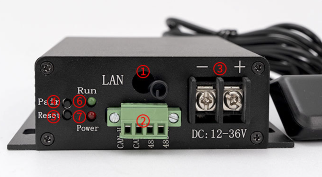
① Remote control antenna: This is an optional feature. The remote control receiving antenna is
omitted from products without remote control functionality.
② RS485 and CAN communication interfaces; please refer to the silkscreen information on the
casing for detailed signal definitions.
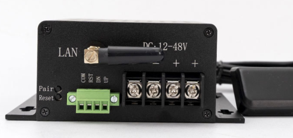
③ The power supply interface only allows input of 12~36V DC voltage.
④ Remote pairing button: Press and hold the pairing button for 5 seconds. The operation
indicator light will change from slow flashing to rapid flashing, indicating that the controller
has entered remote pairing mode. At this time, you can operate the remote control to pair
the controller.
⑤ Push rod reset button: Press and hold this button for 5 seconds to start the push rod reset.
Do not release the button during the reset process until it is complete. Releasing the button
midway will stop the push rod.
⑥ System operation indicator light
⑦ Controller power indicator
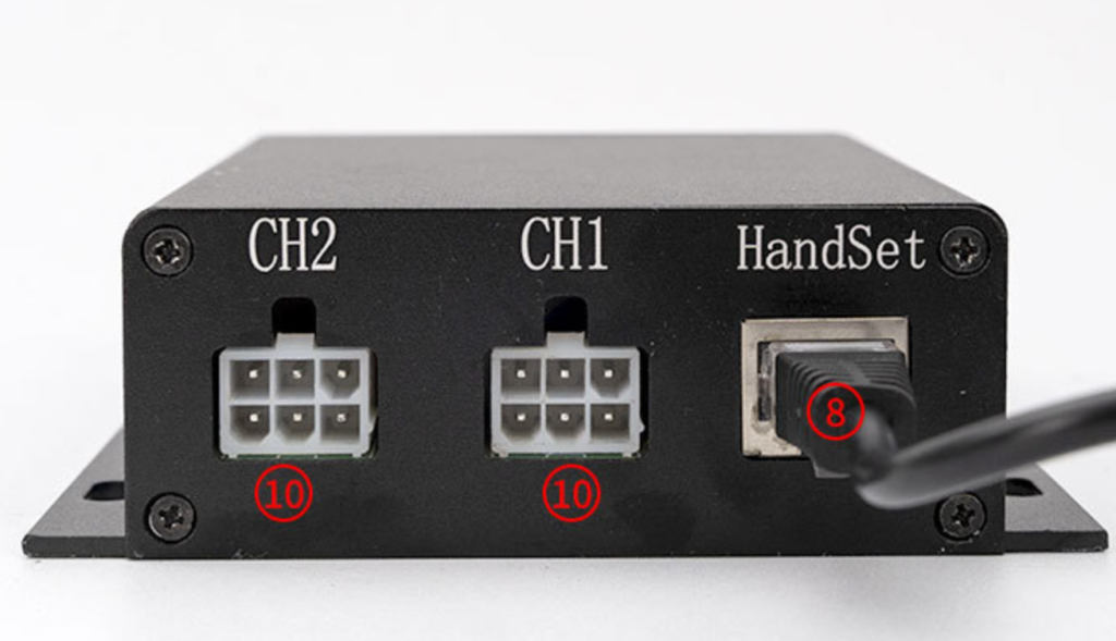
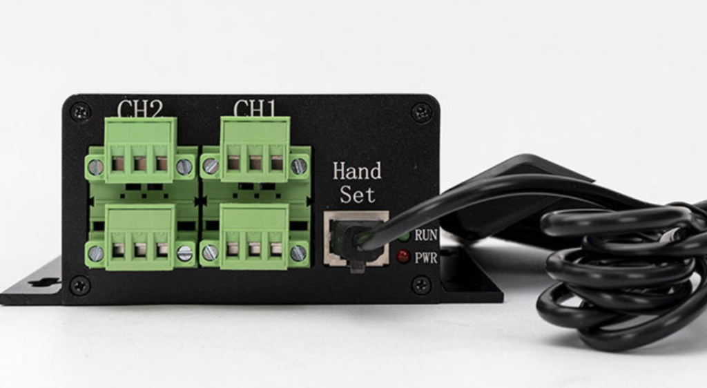
⑧ Gamepad interface/touchscreen interface
⑨ Channel 1 Electric Actuator Interface
⑩ Channel 2 Electric Actuator Interface
| Signal | Function Description | Push rod interface signal label |
| Positive terminal | Push Rod Motor Positive Wiring | 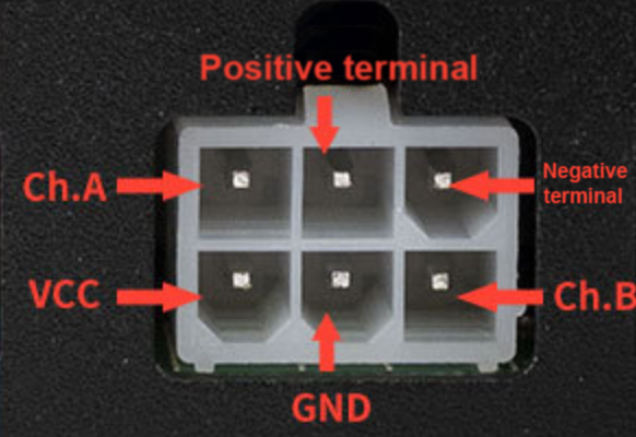 |
| Negative terminal | Push Rod Motor Negative Wiring | |
| VCC | Hall Power Supply Positive Wiring | |
| GND | Hall Power Supply Negative Wiring | |
| Ch.A | Hall Signal A | |
| Ch.B | Hall Signal B |
| Number | Controller Interface | Function Description |
| 1 | Pari | To enter pairing mode, press and hold the remote control pairing button for 5 seconds. |
| 2 | Reset | Press and hold the push rod reset button for 5 seconds to start the reset process. Do not release the button during the reset. |
| 3 | LAN | Remote control antenna |
| 4 | 485-A/485-B | RS485 communication bus interface |
| 5 | CAN-H/CAN-L | CAN communication bus interface |
| 6 | Hand Set | Handset interface / Debug touchscreen interface |
| 7 | PWR | Power indicator light |
| 8 | RUN | Run indicator light, running status indicator, error code indicator |
| 9 | CH1-CH4 | Actuator interface (motor interface + Hall effect signal interface) |
| 10 | +- | External power supply interface (DC: 12-36V) |
| Number | Signal Definitions | Push rod interface signal label |
| 1 | Motor Negative Terminal | 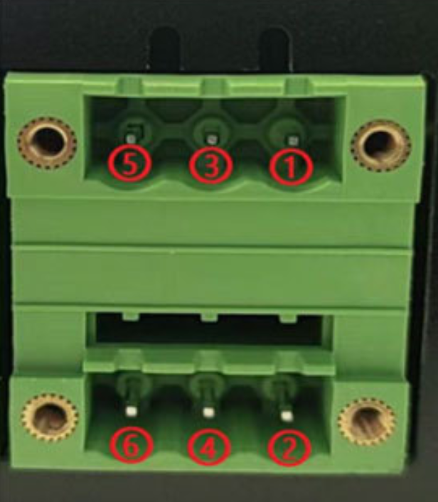 |
| 2 | Hall B | |
| 3 | Hall Positive Terminal | |
| 4 | Hall Negative Terminal | |
| 5 | Motor Negative Terminal | |
| 6 | Hall A |
| Number | Signal definition | Function Description | network port |
| 1 | SWDIO | System debugging signals | 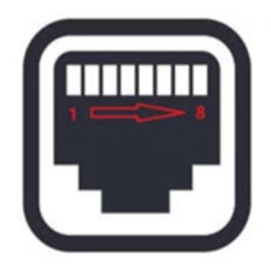 |
| 2 | SWCLK | System debugging signals | |
| 3 | RX – Gamepad | Handheld serial port transmit signal | |
| 4 | TX – Gamepad | Handheld serial port receive signal | |
| 5 | RX – Touchscreen | Debug touchscreen serial port transmit signal | |
| 6 | TX – Touchscreen | Debug touchscreen serial port receive signal | |
| 7 | +5V | External power supply positive | |
| 8 | GND | External power supply negative |
The wired handle uses touch controls to raise and lower the electric linear actuator, and features a data display function that shows real-time actuator height information or controller alarm information. It supports 6-way touch button functionality, with button operation support and audible prompts. The handle connects to the controller’s HandSet port via an RJ45 connector for communication control.
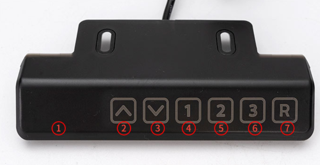
| ① | Display Area | Data display area, real-time display of push rod height position, system error codes |
| ② | Up Button | Press and hold: Push the lever up
Release: Push the lever to stop |
| ③ | Down Button | Press and hold: Lower the lever;
Release: Stop the lever |
| ④ | 1 #Memory Button | Long press the memory button: the display flashes, and the current position is saved to the button
Short press the memory button: the slider automatically moves to the saved position |
| ⑤ | 2 #Memory Button | |
| ⑥ | 3 #Memory Button | |
| ⑦ | Reset Button | Press and hold the reset button, then push the lever to reset. This is necessary for initial installation or in case of an error alarm in the controller |
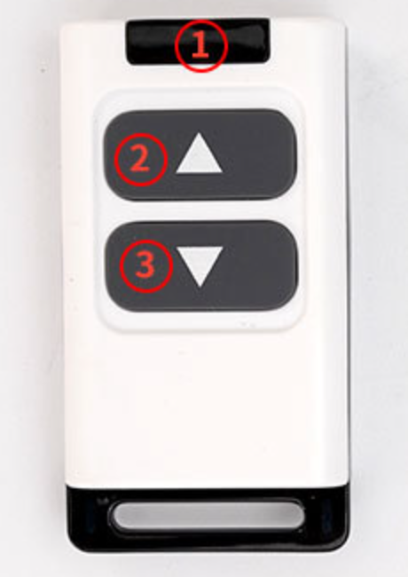
| Number | Function Description |
| ① | Data transmission indicator light |
| ② | up button |
| ③ | down button |
| Remote Control User Manual
1. Pressing any button sends data to the remote control, and the indicator light flashes 2. The up/down buttons perform jog/chain operation according to the controller’s “Remote Control Type” setting. 3. Pressing both the up and down buttons simultaneously for 5 seconds resets the push rod. Remote Control Pairing Procedure 1. First, operate the controller to enter remote control pairing mode. 2. Press any button on the 433M remote control to pair. Note: One 433M remote control can be paired with multiple controllers simultaneously, and one controller can be paired with multiple 433M remote controls. |
|
| Number | Function Description | 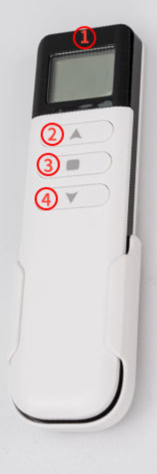 |
| ① | Data display area | |
| ② | Up button | |
| ③ | Stop/Reset button | |
| ④ | Down button | |
| Remote Control User Manual
1. A solid-on network icon in the upper left corner of the screen indicates normal communication, while a flashing icon indicates a communication problem. 2. The battery icon in the upper right corner of the display shows the current remaining battery power of the remote control. 3. The up/down buttons perform momentary/continuous operation according to the “Remote Control Type” setting on the controller. Remote control pairing process instructions 1. First, operate the controller to enter remote control pairing mode. 2. Simultaneously press the Up and Down buttons five times in quick succession to enter pairing mode. 3. In pairing mode, the height information display on the remote control will flash “ —”. 4. The number at the CH position increasing from 1 to 50 indicates that pairing data is being successfully sent. 5. After pairing is complete, both the remote control and the controller will automatically exit pairing mode. Note: One 2.4G remote control can only operate one controller, but one controller can be paired with multiple 2.4G controllers. However, multiple 2.4G trackers paired with the same controller cannot be used simultaneously. |
||
| Error Codes | Processing logic |
| E01: Obstacle Encounter and Backtrack | When the push rod encounters resistance during its movement, the error code is automatically cleared after it retracts. |
| E02: Synchronization Deviation Alarm | In extreme abnormal situations, if the push rods are out of sync and the Hall effect deviation between channels exceeds the set value, an alarm will be triggered. |
| E03: Low Voltage Warning | If the input voltage is lower than the minimum allowable voltage, check if the power supply is normal. |
| E04: Tilt Warning | Desktop tilt alarm, lever stops, system reset required to clear error code. |
| E05: Channel 1 Overcurrent | If the single-channel actuator experiences an overcurrent, check if the actuator load exceeds the allowable range. |
| E06: Channel 2 Overcurrent | |
| E07: Channel 3 Overcurrent | |
| E08: Channel 4 Overcurrent | |
| E09: Power Overcurrent | If the total power supply current is too high, check if the load is too heavy. |
| E10: Channel 1 Hall Effect Signal Not Received | If a single actuator has no Hall signal, check the connection between the actuator and the controller for reliability, check for actuator stall, and reset the system to clear the error code. |
| E11: Channel 2 Hall effect sensor no signal | |
| E12: Channel 3 Hall effect sensor no signal | |
| E13: Channel 4 Hall effect sensor no signal | |
| E14: Overheat warning | Overheating alarm for push rod; error code will automatically clear during the rest period. |
| E15: Incorrect password | This controller is unregistered and being used illegally. Registration is required for its use. |
| E16: Abnormal power failure alarm | If the power is interrupted during the operation of the push rod, a reset is required to clear the error. |
1. Normal Operation Status: The green LED light illuminates for 0.5 seconds, then turns off for 0.5 seconds, flashing slowly once every 1 second.
2. Remote Control Pairing Status: The green LED light illuminates for 0.2 seconds, then turns off for 0.2 seconds, flashing rapidly once every 0.4 seconds.
3. Error Code Display Status: When a system malfunctions and generates an error code, the LED indicator will automatically enter error code display status. After the error code is cleared, the LED indicator will automatically return to normal operation status. The error code display process is as follows; repeat this process until the error code disappears.
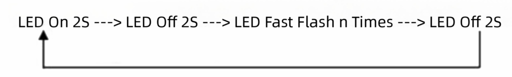
We need to confirm the exact number of times the flashing occurs (n times). For example, if n=2, the corresponding error code would be E02: Synchronization Deviation Alarm.