
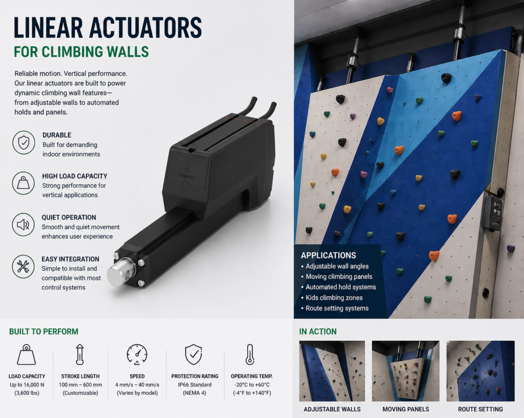
An actuator for an adjustable climbing wall is a heavy-duty motion system, not a simple convenience accessory. In a commercial climbing gym, the wall can weigh hundreds or thousands of kilograms, and the safety requirement is much higher than for light furniture or small fitness equipment.
This guide explains how to think about linear actuator selection for bottom-hinged adjustable climbing walls. It covers the force model, preliminary actuator ranges for different wall sizes, and the safety points that should be treated as non-negotiable.
Interactive Angle Adjustment Demo
The animation below shows the basic motion concept: a bottom-hinged climbing wall changes angle as the rear linear actuator extends and retracts.
Quick Recommendation
For commercial climbing walls, use multiple heavy-duty linear actuators with mechanical self-locking, synchronized control, limit protection, and an operating process that prevents angle adjustment while anyone is climbing.
- Small wall: 2 actuators, 6,000–10,000 N each.
- Medium wall: 2–4 actuators, 10,000–20,000 N each.
- Large wall: 4–6 actuators, ≥20,000 N each, or consider hydraulic cylinders.
Basic Force Model
A typical adjustable climbing wall uses a bottom hinge fixed to the floor or base frame. The actuator is mounted behind the wall and pushes the structure forward to create an overhanging angle. A common adjustment range is from vertical to about 20° overhang, although the exact range depends on the wall design.
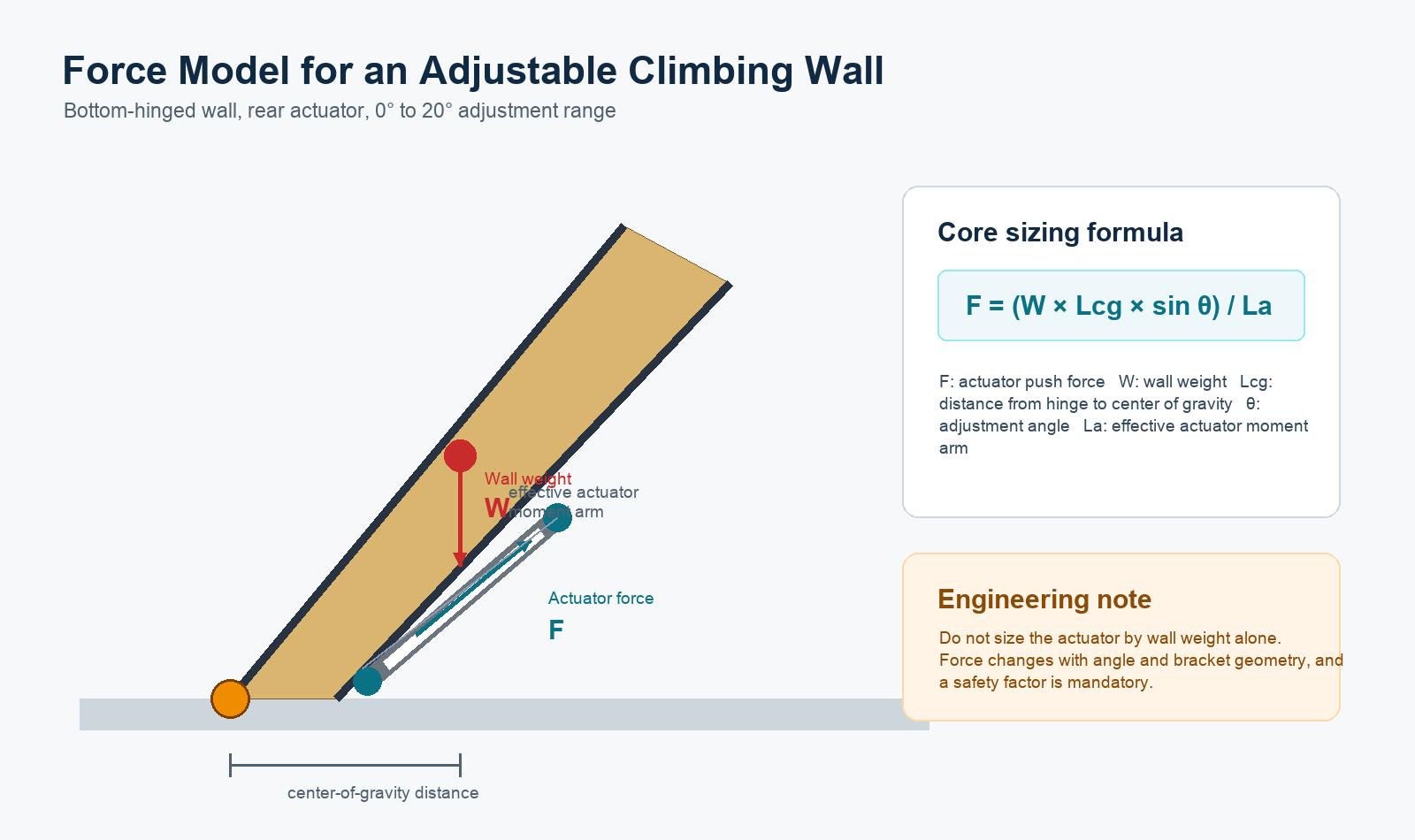
The core calculation is:
Actuator force = (wall weight × center-of-gravity distance × sin adjustment angle) ÷ actuator moment arm
This means the actuator should not be sized by wall weight alone. The hinge position, actuator mounting point, wall thickness, center of gravity, and maximum angle all change the required push force. A safety factor is also required because a climbing wall is a public-use structure with high liability.
Three Preliminary Selection Ranges
The following ranges are starting points for discussion. Final actuator sizing should be confirmed from actual wall drawings, frame material, hinge layout, and local safety requirements.
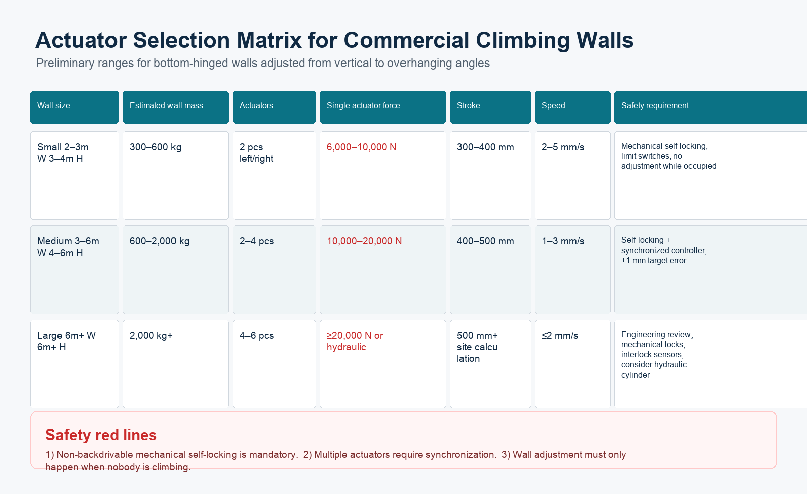
Small Wall: 2–3 m Wide, 3–4 m High
- Estimated wall mass: 300–600 kg
- Actuator quantity: 2 units, left and right symmetrical layout
- Single actuator force: 6,000–10,000 N
- Stroke: 300–400 mm
- Speed: 2–5 mm/s
- Voltage: 24 V DC
- Locking: mechanical self-locking required
Medium Wall: 3–6 m Wide, 4–6 m High
- Estimated wall mass: 600–2,000 kg
- Actuator quantity: 2–4 units
- Single actuator force: 10,000–20,000 N
- Stroke: 400–500 mm
- Speed: 1–3 mm/s
- Voltage: 24 V DC
- Control: synchronized controller recommended, target position error within ±1 mm where practical
Large Wall: 6 m+ Wide, 6 m+ High
- Estimated wall mass: above 2,000 kg
- Actuator quantity: 4–6 units
- Single actuator force: 20,000 N or higher
- Stroke: 500 mm or more, based on site calculation
- Speed: 2 mm/s or slower
- Power: 24 V DC actuator system or hydraulic solution
- Engineering requirement: structural review, mechanical locking, synchronization, and interlock protection
Product Parameter Selection Example
For a typical mid-size commercial adjustable climbing wall, assume a bottom-hinged wall about 4 m wide and 5 m high, with an estimated moving mass of 1,200 kg and a target adjustment range of 0–20 degrees. The exact force must still be checked against the final hinge position, actuator mounting angle, wall structure, and safety factor, but the example below shows how each actuator parameter is selected.
| Parameter | Example Selection | Why This Choice Matters |
|---|---|---|
| Actuator quantity | 2–4 synchronized actuators | A mid-size wall is too wide and heavy for a single point drive. Symmetrical mounting helps reduce twisting, while feedback-based synchronization keeps both sides moving together. |
| Rated force | 10,000–20,000 N per actuator | The force range comes from wall mass, center-of-gravity distance, maximum angle, and actuator moment arm. A safety factor should be added because climber holds, wall panels, and frame weight vary by project. |
| Stroke | 400–500 mm | The stroke must cover the full 0–20 degree travel without forcing the actuator into a poor angle near either end of movement. Final stroke should be confirmed from a side-view linkage drawing. |
| Speed | 1–3 mm/s | Slow movement is preferred for heavy sports equipment. It gives staff better control and reduces shock load on the frame, hinge, and mounting brackets. |
| Voltage | 24 V DC | 24 V DC is common for commercial equipment controls and works well with limit switches, synchronized controllers, and safety interlock circuits. |
| Holding method | Mechanical self-locking / non-backdrivable drive | The actuator must hold the wall angle during power loss. This is a safety requirement, not a convenience feature. |
| Control system | Feedback synchronization with safety interlock | Multiple actuators should stay within a tight position tolerance, and adjustment should be disabled unless the wall is clear of climbers. |
This example is a preliminary selection path, not a final engineering approval. Before production, the wall manufacturer should confirm bracket strength, hinge load, emergency stop logic, limit switch positions, and local safety requirements.
Safety Points That Are Not Optional
1. Mechanical self-locking is mandatory
The wall must hold its angle when power is off. In heavy-load climbing wall applications, ordinary actuators may creep or back-drive. Use a non-backdrivable actuator design, such as a worm-gear or mechanical locking structure, and add mechanical stops or secondary locking where required.
2. Multiple actuators must be synchronized
If two or more actuators move out of sync, the wall frame can twist. For medium and large walls, use a synchronized control system with feedback. Hall sensors or potentiometer feedback can help keep both sides moving together.
3. Adjustment must happen with no climber on the wall
The control logic should prevent movement while the wall is occupied. A practical design may include a staff-only control switch, hold-to-run operation, warning light, physical lockout process, or sensor-based interlock.
When to Consider Hydraulic Cylinders
When the required force per actuator exceeds about 20,000 N, a hydraulic cylinder may be more mature for very large climbing wall structures. Hydraulics can provide very high force and can use hydraulic locking, but they require a pump station, hoses, seals, maintenance, and more complex installation.
For small and medium adjustable walls, electric linear actuators are cleaner, easier to wire, and simpler to integrate. For very large walls, the final choice should be made after structural calculation and risk assessment.
What Information Is Needed for Accurate Sizing?
To calculate the actuator force more accurately, prepare:
- Wall width, height, and thickness
- Wall material and estimated total mass
- Hinge position and wall center of gravity
- Target angle range, such as 0° to 20°
- Available actuator mounting points
- Number of actuators allowed by the structure
- Required speed and adjustment frequency
- Safety lock, limit switch, and interlock requirements
If the design involves vertical lifting instead of wall angle adjustment, an electric lifting column may be a better solution. For guidance on column selection, see GeMinG’s article on choosing fully automatic electric lifting columns.
FAQ
Can one actuator adjust a commercial climbing wall?
Usually no. Commercial walls should normally use at least two actuators for balanced left-right support. A single actuator may only be suitable for very small test structures.
Why is self-locking so important?
The wall must not move or fall when power is off. Mechanical self-locking and secondary mechanical support are key safety requirements in heavy climbing wall applications.
What speed is suitable for wall angle adjustment?
Slow movement is safer. Small walls may use 2–5 mm/s, medium walls often use 1–3 mm/s, and large walls should usually move at 2 mm/s or slower.
Do multiple actuators need feedback?
Yes. Feedback helps the controller keep actuators synchronized and reduces the risk of wall twisting.
When is hydraulic better than electric?
For very large walls or when the force requirement exceeds about 20,000 N per actuator, hydraulic cylinders may be more suitable, although they add pump, hose, and maintenance complexity.