
Download PDF datasheet for embodied robot columns.
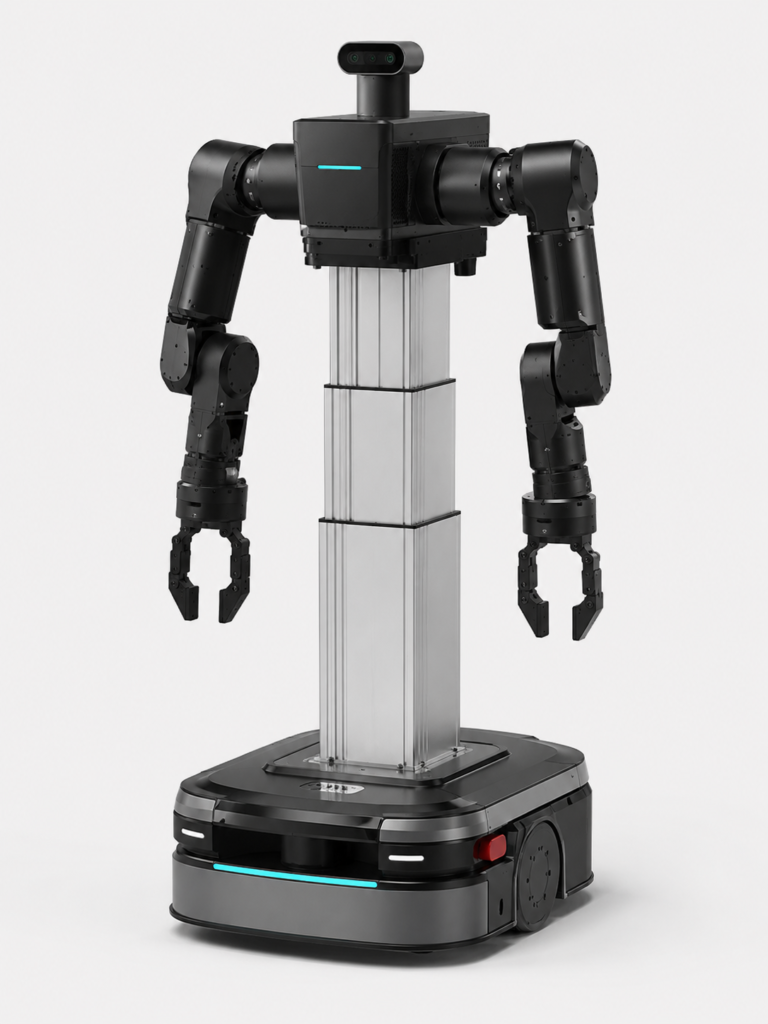
Embodied robots are no longer simple mobile platforms. Many new robotic systems now integrate lifting modules, dual-arm manipulators, vision systems, sensors, and workstation docking functions into one compact mobile robot body.
For this type of robot, the lifting column is not just a height-adjustment device. It becomes part of the robot’s structural frame, motion system, and cable-management design.
GeMinG provides intelligent lifting columns for embodied robots, mobile robots, service robots, AGV/AMR platforms, and dual-arm robotic systems. These columns are designed for precise lifting motion, stable load support, and communication with the robot control system.
Why Embodied Robots Need a Lifting Column
A lifting column allows the robot to adjust its working height for different tasks, such as:
- Picking objects from shelves or workbenches
- Adjusting the height of a dual-arm shoulder plate
- Docking with workstations or production equipment
- Raising cameras, sensors, or perception modules
- Improving the working range of robotic arms
- Adapting to different human-machine interaction heights
For dual-arm mobile robots, the lifting column must handle not only vertical load, but also off-center load, bending moment, vibration, acceleration, and possible impact during movement.
Comparison Chart of GEMING Lifting Columns for Embodied Robots
| Model | HTD3-12 Compact Square Lifting Column | HTD3-14 Square Lifting Column | HTA3 Rectangular Lifting Column |
|---|---|---|---|
| Tube size | 125 × 125 mm square column | 142 × 142 mm square column | 193 × 141 mm rectangular column |
| Voltage | 24V, 48V DC | 24V, 48V DC | 24V, 48V DC |
| Motor | DC servo motor 400w | DC servo motor 400w | DC servo motor 400w |
| Maximum thrust / pull | 500N / 500N | 1500N / 1500N | 1500N / 1500N |
| Maximum speed | 0–60 mm/s | 0–150 mm/s | 0–150 mm/s under 800N load |
| Closed height | Stroke / 2 + 250 mm | Stroke / 2 + 250 mm | Stroke / 2 + 250 mm |
| Dynamic lateral torque | 500 Nm | 500 Nm | 800 Nm |
| Static lateral torque | 700 Nm | 700 Nm | 1000 Nm |
| Communication | CANopen / EtherCAT / RS485 | CANopen / EtherCAT / RS485 | CANopen / EtherCAT / RS485 |
| Protection rating | IP54 | IP54 | IP54 |
| Wiring method | Internal wiring, customizable | Internal wiring, customizable | Internal wiring, customizable |
| Recommended application | Compact mobile robots, sensor-lifting modules, light-duty robotic arms, and space-limited robot designs | Medium-duty embodied robots, service robots, AGV/AMR platforms, and square-column robot structures | Dual-arm mobile robots, heavier top-mounted modules, and applications requiring higher structural stability and lateral torque capacity |
Model Selection Notes
For compact robots or sensor-lifting applications, HTD3-12 is usually sufficient. For medium-duty embodied robots requiring a square column structure, HTD3-14 is a practical option. For dual-arm mobile robots or applications with higher off-center load and lateral moment requirements, HTA3 is usually the preferred model because of its larger rectangular tube structure and higher lateral torque capacity.
Why Bending Moment Matters More Than Weight
For a robot lifting column, vertical load is only one part of the selection process.
In many embodied robot applications, the top-mounted structure is not centered. A shoulder plate, dual arms, cameras, sensors, or tool modules may be mounted away from the column centerline. This creates a bending moment.
The basic calculation is:
Bending moment = Load force × offset distance
For example, if a 20 kg dual-arm assembly is mounted 200 mm away from the column centerline:
20 kg × 9.81 × 0.2 m = approximately 39 Nm
This static moment may look small compared with the rated moment of the column. However, real robot operation also includes:
- Arm acceleration and deceleration
- Emergency stop
- Payload changes
- Mobile base vibration
- Collision or impact
- Working at full extension
- Repeated motion cycles
Therefore, the final selection should consider both static and dynamic working conditions.
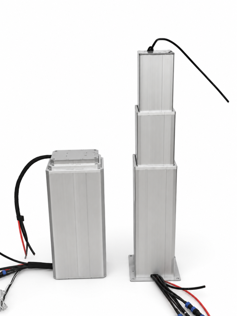
Internal Wire Routing
For robotic applications, internal wire routing is often required when the customer wants the wiring harness to pass through the lifting column.
Internal wire routing can make the robot cleaner, safer, and easier to integrate. It helps protect cables from external impact and reduces the risk of cables being pulled, twisted, or damaged during robot operation.
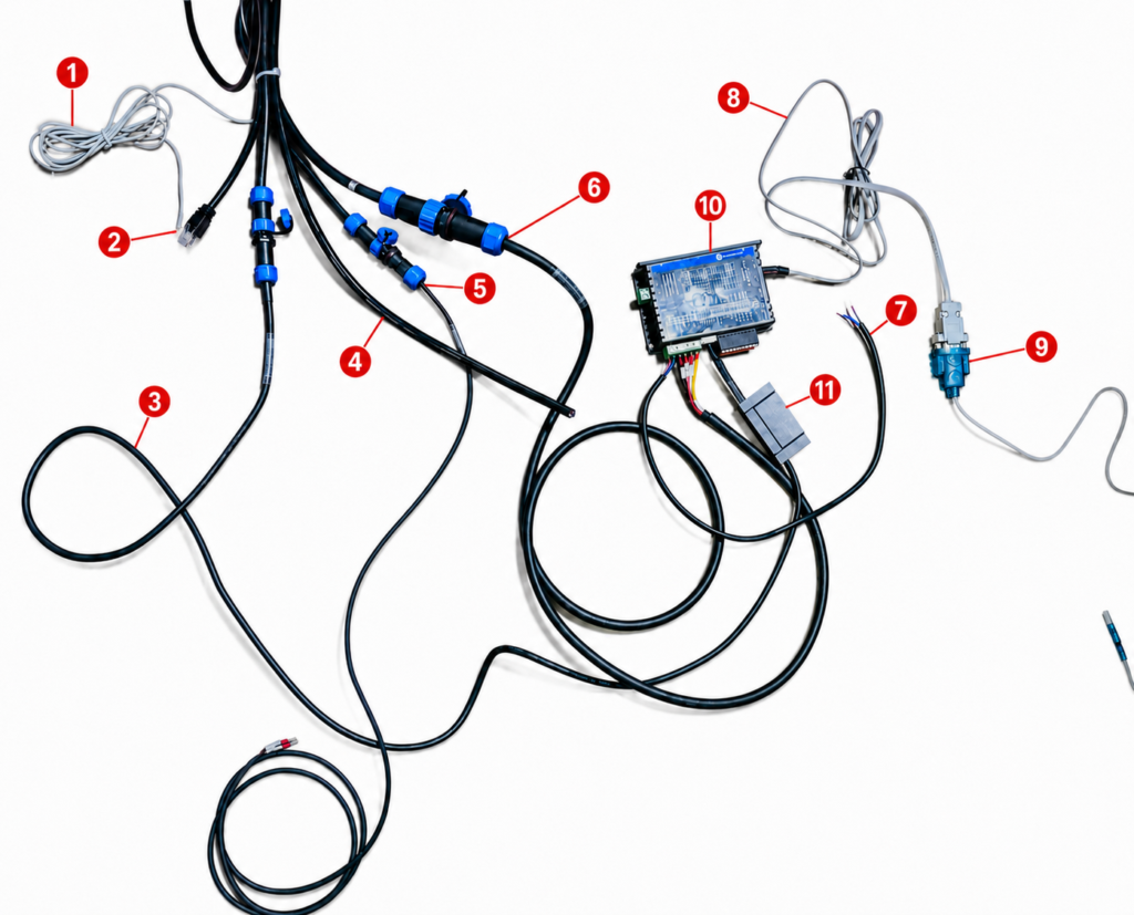
A typical internal wire routing system may include:
- Homing signal wire
- RJ45 patch cords
- Encoder cable
- Output power cable
- Brake cable
- Motor power cable
- Input power cable
- Debug cable
- Customer connection cable
- Driver
- Encoder
Internal wiring is recommended when the robot requires a compact and enclosed structure, especially for mobile robot platforms, service robots, and embodied robots with external covers.
However, internal wire routing must be confirmed before production. The required cable type, connector size, cable quantity, bending space, and signal shielding requirements all affect the final design.
External Cable Routing with Cable Chain
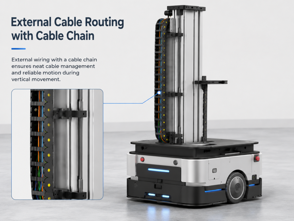
If the customer does not need internal wire routing, the wiring harness can be arranged externally with a cable chain.
External cable routing is easier to maintain and usually more flexible for testing or prototype-stage robots. It is also useful when the wiring harness is too large or too complex to pass through the column internally.
External cable chain routing may be preferred when:
- The robot is still in the prototype stage
- The wiring harness is frequently changed
- The customer needs easier maintenance
- The cable connectors are too large for internal routing
- The application accepts visible external cables
- The column is installed inside another robot frame or cover
For production robots, internal wire routing usually gives a cleaner appearance. For prototype robots, external cable chain routing may be faster and easier to debug.
Control and Communication Options
The embodied robot lifting column can be configured with servo control and communication options according to the robot controller.
Available communication protocols include:
- RS485
- CANopen
- EtherCAT
The column can support soft limits, mechanical limits, position control, and integration with the robot control system. For applications requiring precise height adjustment, we recommend using the matched driver/controller instead of driving the motor directly.
Power-Off Holding and Brake Requirement
For robotic systems, especially dual-arm mobile robots, power-off holding is important.
The lifting column uses a ball screw structure. A ball screw provides high efficiency and smooth movement, but it should not be treated as naturally self-locking in the same way as a trapezoidal screw.
If the robot must hold position safely during power loss, a holding brake or servo brake configuration is recommended.
This is especially important when:
- A dual-arm module is mounted on top
- The robot carries payloads
- The column works at a high position
- The robot may experience vibration or emergency stop
- Safety during power loss is required
Information Needed for Quotation
To recommend the correct lifting column, please provide the following information:
- Model: please choose from the catalog
- Voltage: 48V DC(default)
- Motor: 400W(default)
- Load:
- Stroke:
- Speed:
- Communication protocol: RS485 / CANopen / EtherCAT
- Do you require internal wire routing for the wiring harness?
- Quantity:
For dual-arm robot applications, we also recommend providing:
- Total top-mounted weight
- Center-of-gravity offset from the column centerline
- Maximum payload on each arm
- Maximum working height
- Required lifting speed
- Whether a power-off holding brake is required
- Top mounting plate or shoulder bracket drawing
Conclusion
A lifting column for embodied robots should not be selected only by vertical load. The correct selection must consider stroke, closed height, bending moment, speed, communication protocol, wiring method, and power-off safety.
For compact robots, HTD3-12 may be suitable. For medium-duty square-column robot structures, HTD3-14 is a practical option. For dual-arm mobile robots or applications requiring higher structural stability, HTA3 is usually the better choice.
GeMinG can customize stroke, closed height, wiring method, communication protocol, top/bottom mounting plates, and control configuration according to the robot design.
YES, the column has self-locking on power loss.
YES, we offer servo motor with an integrated driver.
CAN-FD protocol is not supported at present. If you only require the CSP mode available under CAN-FD protocol, please specify this when placing your order, and we will equip Kinco motors to realize CSP mode for you.