
A cobot lifting column is a guided vertical axis that raises or lowers a collaborative robot, tool, sensor, or work platform. It extends the useful work envelope when one cobot must reach machines, shelves, fixtures, or inspection points at different heights.
Selection should be based on the complete moving mass, center-of-gravity offset, required stroke, speed, duty cycle, controls, mounting stiffness, and machine safety—not rated thrust alone.
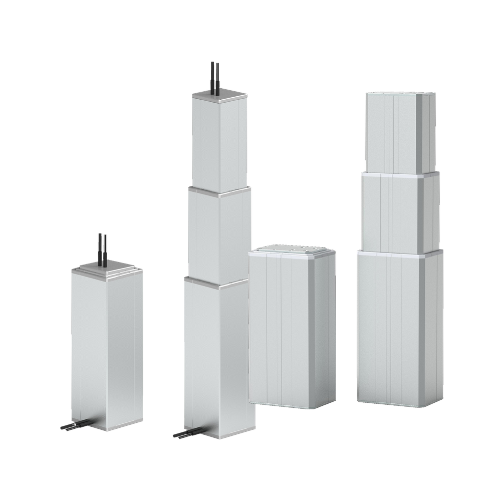
Why a cobot lifting column extends the work envelope
A fixed collaborative robot can only reach points inside its normal three-dimensional work envelope. Moving the complete robot vertically shifts that envelope up or down without asking the arm to operate continuously near an awkward joint limit.
- Load and unload machines with doors, chucks, or trays at different heights
- Serve several vertically arranged fixtures with one robot
- Adjust camera, scanner, or inspection height
- Raise an AMR-mounted manipulator after the mobile base reaches the work point
The lifting column is part of the machine structure. Its mounting, load path, cable routing, and control behavior must therefore be reviewed with the cobot and its payload.
Cobot lifting column vs linear actuator
A lifting column contains a guided telescopic structure designed for upright motion and can help resist offset loading. A linear actuator creates push-pull motion but may require a separate guide, frame, or bearing system.
Neither option is automatically better. A guided column often suits a compact vertical robot axis. A linear actuator can be appropriate when the machine already provides accurate external guidance. Compare the complete mechanical arrangement rather than thrust figures alone.
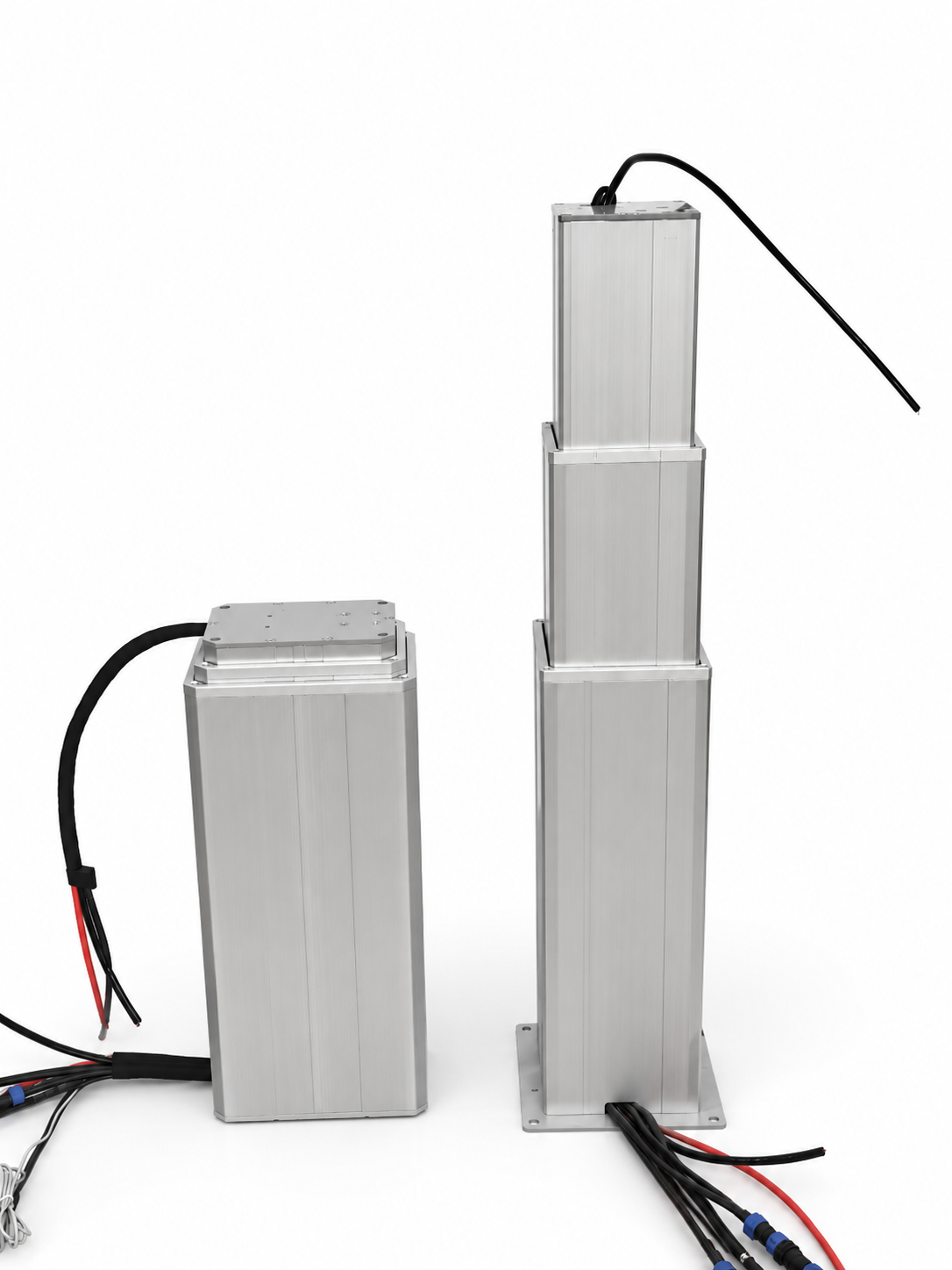
Cobot lifting column selection inputs
- Moving mass: include the cobot, tool, cables, fixture, adapter plates, and maximum payload.
- Center-of-gravity offset: measure the horizontal distance from the column centerline to the combined center of gravity.
- Stroke and closed height: define the useful travel, end clearances, and available installation envelope.
- Motion profile: specify speed, acceleration, stops per cycle, cycles per hour, and duty cycle.
- Controls: define supply voltage, position feedback, command interface, limit handling, and fault behavior.
- Environment: consider dust, moisture, cleaning, temperature, vibration, and moving-cable requirements.
- Mounting: provide the base plate, top adapter, bolt pattern, frame stiffness, and orientation.
Product parameter selection example
Assume the cobot, tool, cables, adapter, and maximum payload have a combined mass of 55 kg. Their combined center of gravity is 300 mm from the lifting-column centerline. The application needs 700 mm of useful vertical travel and 12 moves per hour.
First calculate the static gravitational force from the complete moving mass. Next calculate the offset moment using the 300 mm horizontal distance. Apply the dynamic and safety factors approved for the machine. Then verify usable stroke, closed height, target speed, stopping behavior, duty cycle, brake or load-holding requirement, mounting stiffness, and mobile-base stability if applicable.
Design note: This example explains the selection process and is not a model recommendation. Final selection requires the real motion profile, mounting drawing, and complete robot layout. The multi-stage column height calculator can help compare stroke and installation height.
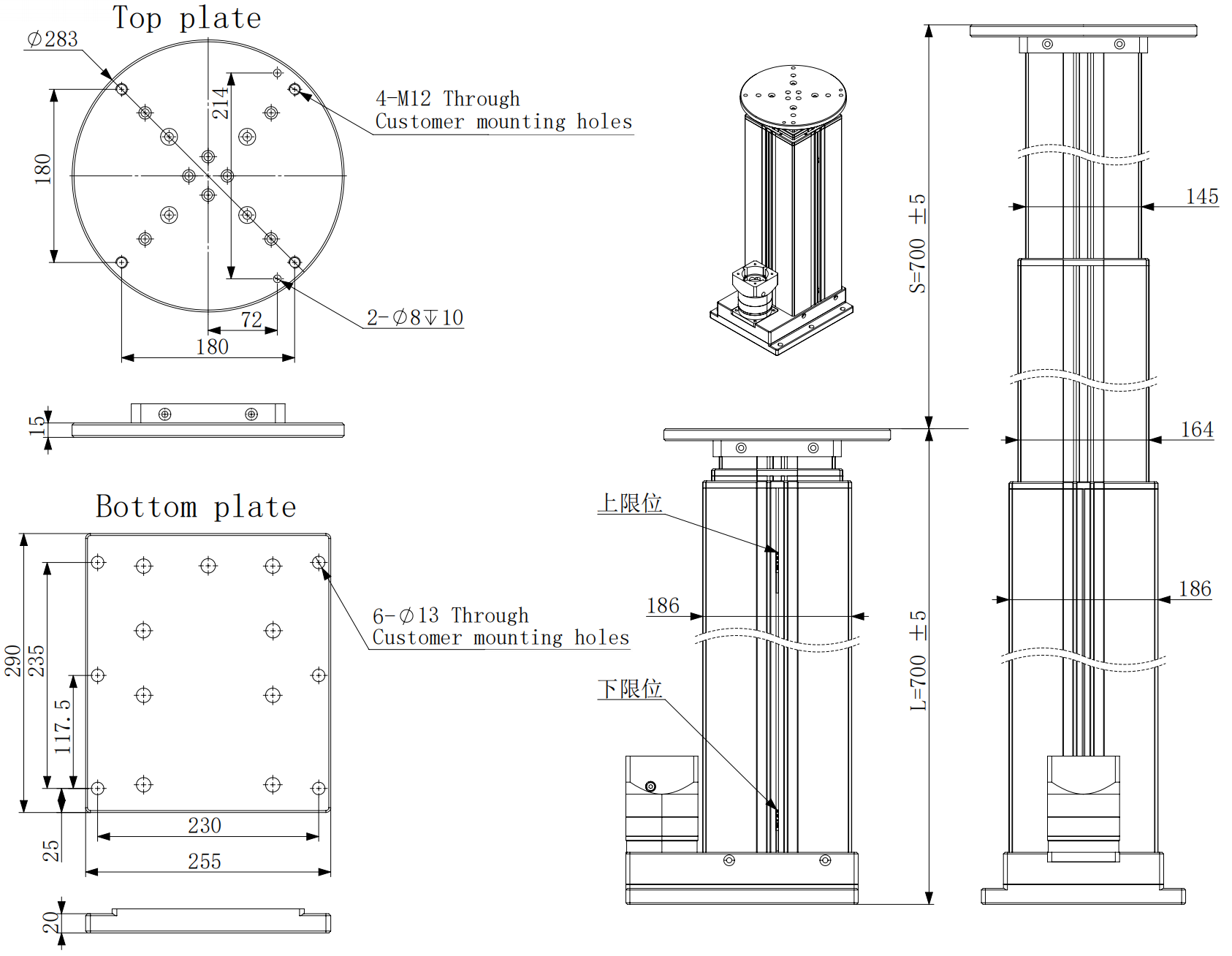
Integration, controls, and safety
The vertical axis must coordinate with the cobot controller and the machine safety system. Define position feedback, software and hardware travel limits, emergency-stop behavior, restart rules, safe speed, load holding, and fault recovery before commissioning.
A brake or another holding method may be required when the load must remain in place after power loss. The system integrator remains responsible for the complete risk assessment, including pinch points, base stability, cable movement, guards, access to the moving area, and the effect of the highest position on an AMR or AGV.
Typical cobot lifting column applications
- Machine tending: move one cobot between loading points at different heights.
- Inspection: position cameras, scanners, or sensors above parts and fixtures.
- Mobile manipulation: add a deployable vertical axis to an AMR-mounted robot.
- Laboratory and test equipment: align tools or samples with several vertical work levels.
GEMING vertical motion options
GEMING supplies electric lifting columns, linear actuators, and control options for industrial equipment. The embodied robot pillar is one product route for robot height adjustment. Model suitability depends on the actual load, offset, travel, motion profile, mounting, controls, and environment.
What to prepare before a technical review
- Maximum moving mass and payload
- Center-of-gravity position and maximum horizontal offset
- Required stroke, closed height, speed, and movement frequency
- Base and top mounting drawings
- Voltage, feedback, controller interface, and safety requirements
- Temperature, dust, moisture, cleaning, and cable-routing conditions
Frequently asked questions
What is a cobot lifting column?
A cobot lifting column is a guided electric vertical axis that raises or lowers a collaborative robot, tool, sensor, or work platform.
When should a cobot use a lifting column?
It is useful when the robot must work at several heights and the machine needs guided, compact vertical motion. A linear actuator may fit when another structure already guides the moving load.
What information is needed to select the vertical axis?
Provide the complete moving mass, center-of-gravity offset, stroke, closed height, speed, duty cycle, mounting layout, voltage, controls, and environment.
Can a cobot lifting column be used on an AMR or AGV?
It can be considered when the mobile base, brakes, column, mounting, and controls are designed for the moving load. Stability must be checked at the highest position and during travel.
Is rated thrust enough to select a column?
No. Selection must also account for offset moment, side force, motion profile, mounting stiffness, duty cycle, stopping behavior, and system safety.
Request a technical review
Send the load, center-of-gravity offset, stroke, speed, duty cycle, mounting drawing, voltage, controls, and environment through the contact page.