
CAN bus is widely used in industrial automation, mobile machinery, robotics, medical equipment, and intelligent lifting systems. Many customers request a lifting column “with CAN bus” because they want to connect the actuator or lifting column directly to their own controller, PLC, robot controller, or embedded platform such as Jetson.
However, one important point is often misunderstood:
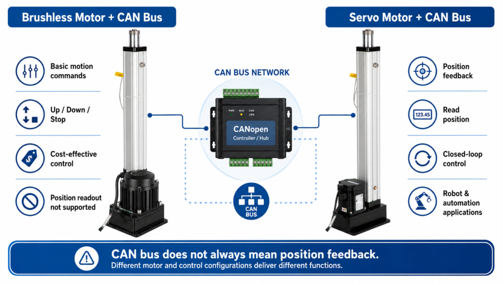
CAN bus is a communication interface. It does not automatically mean that the device can provide position feedback or support “read position” commands.
Whether a lifting column can report its actual position depends on the internal motor type, feedback device, motor driver, controller software, and supported communication protocol.
At GEMING, CAN bus lifting columns are mainly available in two technical configurations:
- Brushless motor + CAN bus
- Servo motor + CAN bus
These two solutions are not the same. They are designed for different levels of control requirement.
1. What Is CAN Bus?
CAN stands for Controller Area Network. It was originally developed for reliable communication between electronic control units and is now widely used in industrial and mobile control systems.
In simple terms, CAN bus allows different electronic devices to exchange messages over a shared communication network. It defines how messages are transmitted, identified, prioritized, and checked for communication errors.
But CAN bus itself is mainly a communication layer. It does not define what every product must do after receiving a message.
For example, two devices may both have CAN bus communication, but their supported commands can be very different:
- One device may only accept basic up/down movement commands.
- Another device may support speed control.
- Another device may support actual position feedback.
- A servo drive may support advanced motion control modes under CANopen/CiA 402.
This is why “with CAN bus” should not be understood as “with full servo position control” unless this has been clearly confirmed.
2. CAN Bus Is Not the Same as CANopen Motion Control
CAN bus is the underlying communication technology. CANopen is a higher-level communication protocol built on CAN.
In CANopen systems, the object dictionary, SDO, PDO, and device profiles define how devices exchange configuration data, status data, and process data. For drive and motion control applications, CiA 402 is a widely used CANopen device profile for servo drives, frequency inverters, and stepper motor controllers.
Under a motion-control profile, the system may include objects for target position, actual position, velocity, status word, control word, and operating modes.
This is very different from a basic CAN communication version, where the manufacturer may define only simple proprietary CAN commands, such as:
- Extend
- Retract
- Stop
- Set direction
- Basic status response
Therefore, when a customer needs to read actual position, synchronize multiple columns, or control a robotic system, it is not enough to ask only for “CAN bus.” The exact protocol and feedback requirements must be confirmed before production.
3. Brushless Motor + CAN Bus: Suitable for Basic Command Control
A brushless motor lifting column with CAN bus is suitable when the customer mainly needs digital command control.
Typical functions may include:
- Sending movement commands through CAN
- Start / stop control
- Direction control
- Basic system status, depending on the controller design
- Integration with the customer’s own control system
This solution is usually more cost-effective than a servo solution and is suitable for many industrial lifting applications where high-precision closed-loop position feedback is not required.
However, a brushless motor version does not automatically support actual position reading.
If the motor system does not include an encoder feedback structure and the controller software does not provide position-related CAN data, the customer cannot read the real-time position through CAN.
This does not mean the CAN bus is defective. It simply means the product configuration is designed for command control, not servo position feedback.
Recommended applications:
- Simple electric lifting systems
- Industrial height adjustment
- Equipment lifting where manual or external limit control is acceptable
- Applications where the customer only needs CAN-based movement command
- Projects that do not require closed-loop position feedback
Not recommended when the customer requires:
- Read actual position through CAN
- Closed-loop position control
- Multi-axis synchronization
- Robot motion integration
- High-precision repeatable positioning
- CANopen CiA 402 servo drive behavior
4. Servo Motor + CAN Bus: Suitable for Position Feedback and Advanced Control
A servo motor lifting column with CAN bus is designed for higher-level motion control.
Compared with a basic brushless motor version, a servo system normally includes a motor feedback device such as an encoder. This allows the drive system to know the motor position and provide position-related information to the controller.
Depending on the controller and protocol design, a servo motor + CAN bus solution may support:
- Actual position feedback
- Target position control
- Speed control
- Status monitoring
- More precise repeatable positioning
- Better integration into robot or automation systems
- Possible CANopen motion-control functions, if specified
This configuration is more suitable for applications where the lifting column is not only moving up and down, but also becoming part of a controlled motion system.
Recommended applications:
- Robot lifting axis
- AGV / AMR lifting module
- Collaborative robot height adjustment
- Automated inspection equipment
- Multi-column synchronized lifting
- Laboratory automation
- Smart manufacturing workstations
- Applications requiring position feedback and controlled motion
However, even with a servo motor, the exact protocol still needs to be confirmed. Not every CAN servo system automatically follows the same CANopen profile or exposes the same position objects. Customers should provide their required command list, CAN frame format, CANopen object requirements, or integration standard before ordering.
5. Why Some CAN Bus Products Can Read Position and Others Cannot
The ability to read position depends on several conditions.
1. Feedback hardware
To read actual position, the system needs a way to measure position. This may require an encoder, Hall feedback, potentiometer, absolute sensor, or other position feedback device.
If the motor system does not measure position, the controller cannot report a reliable actual position.
2. Motor driver capability
The driver must be able to process feedback data and make it available to the communication system.
A simple movement controller may only handle direction and stop commands. A servo driver is usually designed to process feedback and control position, velocity, or torque.
3. Controller software
Even if feedback exists internally, the controller software must support a command or object that allows the customer to read this data.
If the software does not expose actual position through CAN, the customer cannot read it from the outside.
4. Communication protocol
CAN bus only provides the communication channel. The actual meaning of each CAN message depends on the protocol.
The protocol may be:
- Manufacturer-defined CAN protocol
- CANopen
- CANopen CiA 402 drive profile
- J1939
- A customized protocol requested by the customer
Only when the protocol defines position feedback can the customer read position through CAN.
6. How to Specify CAN Bus Requirements Before Ordering
To avoid misunderstanding, customers should not only say “we need CAN bus.”
For lifting column projects, especially robot or automation projects, the following points should be confirmed before production:
- Do you need only movement commands, or do you need position feedback?
- What communication protocol do you need?
- What controller will you use, such as PLC, Jetson, robot controller, or custom board?
- Is the lifting column used as a simple actuator or as a robot motion axis?
These questions are especially important for robotics and automation systems.
7. Recommended Selection Guide
| Requirement | Recommended Solution |
|---|---|
| Basic CAN movement command | Brushless motor + CAN bus |
| Start / stop / extend / retract by CAN | Brushless motor + CAN bus |
| Cost-effective lifting control | Brushless motor + CAN bus |
| Read actual position through CAN | Servo motor + CAN bus |
| Closed-loop position control | Servo motor + CAN bus |
| Robot lifting axis | Servo motor + CAN bus |
| Multi-axis synchronization | Servo motor + CAN bus |
| CANopen motion-control integration | Servo motor + CAN bus, protocol confirmed before order |
8. Important Note for Robot Applications
Robot applications usually require more than simple movement control.
If the lifting column is used as part of a robot system, the customer may need actual position feedback, repeatable positioning, speed control, acceleration control, safety monitoring, or synchronization with other axes.
In this case, a basic brushless motor + CAN bus version may not be sufficient.
For robot applications, we recommend confirming the required control logic before quotation. If the customer needs to read position through CAN, the servo motor + CAN bus version should be selected.
9. Conclusion
CAN bus is a communication interface, not a guarantee of position feedback.
A lifting column with CAN bus can have different technical configurations. A brushless motor + CAN bus version may support basic movement commands, while a servo motor + CAN bus version is more suitable for position feedback and advanced motion control.
Before ordering a CAN bus lifting column, customers should clearly confirm whether they need:
- Basic movement command only
- Actual position feedback
- Target position control
- Servo closed-loop control
- CANopen / CiA 402 compatibility
- Customized CAN protocol integration
Clear technical confirmation before production helps avoid misunderstanding and ensures that the correct lifting column solution is selected for the application.
References
[1] Bosch CAN Specification 2.0
[2] Texas Instruments, Introduction to the Controller Area Network
[3] CAN in Automation, CANopen Internal Device Architecture
[4] CAN in Automation, SDO Protocol
[5] CAN in Automation, PDO Protocol
[6] CAN in Automation, CiA 402 CANopen Device Profile for Drives and Motion Control
FAQ
No. CAN bus is a communication interface. Position feedback depends on the motor type, feedback sensor, driver, controller software, and supported protocol. A basic CAN bus actuator may accept movement commands but may not support reading actual position.
A brushless motor + CAN bus solution is usually suitable for basic movement commands such as extend, retract, and stop. A servo motor + CAN bus solution is more suitable for actual position feedback, closed-loop control, and robot or automation applications.
In most cases, yes. Reading actual position through CAN usually requires a motor feedback device such as an encoder and a controller that supports position-related CAN or CANopen commands.
No. CAN bus is the underlying communication network. CANopen is a higher-level protocol built on CAN. Motion-control functions such as target position and actual position are usually defined by the device profile and controller software, not by CAN bus alone.