
This page documents an early telescopic lifting column design study. The concept is being evaluated for installations that require a long vertical travel while keeping the retracted package as short as practical.
The work is centered on engineering trade-offs: stage count, guide overlap, bending stiffness, drive architecture, cable routing, controls, safety, and the validation needed before a design can become a released product.
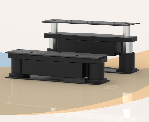
What a telescopic lifting column must achieve
A telescopic lifting column uses two or more nested profiles to provide guided vertical motion. Additional stages can increase the relationship between extended height and retracted height, but each interface adds design work for guidance, overlap, tolerances, synchronization, lubrication, cable management, and structural stability.
The correct architecture depends on the completed machine. A long nominal stroke is not enough: the designer must confirm that the column remains stable under the real payload, offset, acceleration, mounting stiffness, wind or vibration exposure, and duty cycle.
Primary engineering inputs
- Required travel: useful vertical movement after allowing for stops, end clearances, and integration tolerances.
- Retracted and extended envelope: the available installation height and the highest permitted operating position.
- Moving mass: payload, fixture, top plate, cables, sensors, and any moving protective covers.
- Center-of-gravity offset: horizontal distance from the column axis to the combined center of gravity.
- Motion profile: target speed, acceleration, deceleration, stops per cycle, cycles per hour, and required duty cycle.
- Mounting structure: base plate, top interface, bolt pattern, frame stiffness, and orientation.
- Environment: dust, moisture, temperature, cleaning, corrosion, vibration, transport loads, and outdoor exposure.
- Controls and safety: feedback, travel limits, load holding, emergency-stop behavior, obstruction handling, and restart logic.
Stage count, overlap, and stability
A greater number of stages can reduce closed height for a given travel, but it also creates more sliding interfaces. The design must preserve adequate profile overlap throughout the motion. Insufficient overlap can increase play and deflection when the payload is offset.
Profile geometry, guide material, manufacturing tolerance, fastener stiffness, and the surrounding machine frame all affect the result. A lifting column should not be assessed as an isolated axial-force component when the payload creates a bending moment.
Drive and control questions
The drive concept must convert motor torque into predictable vertical motion while meeting speed, load, noise, efficiency, and load-holding requirements. Depending on the application, the design review may compare DC, AC, stepper, or servo drive approaches and suitable screw or transmission arrangements.
Controls are defined at system level. The design team must decide how position is measured, how upper and lower limits are enforced, whether several columns must remain synchronized, and what happens after a power interruption or detected obstruction. A limit switch is not a substitute for closed-loop position feedback when the application needs repeatable intermediate positions.
Prototype validation plan
| Validation area | What should be checked |
|---|---|
| Geometry | Closed height, useful travel, extended height, profile overlap, interference, and cable routing. |
| Structural behavior | Axial load, offset moment, lateral force, deflection, mounting stiffness, and stability at maximum extension. |
| Motion | Speed under load, acceleration, stopping distance, repeatability, noise, vibration, and thermal behavior. |
| Controls | Feedback, limits, synchronization, current monitoring, fault detection, safe stop, and restart behavior. |
| Environment | Temperature, ingress protection, corrosion, contamination, cleaning, transport, and storage conditions. |
| Life testing | Representative load spectrum, cycle count, inspection intervals, wear points, and acceptance criteria. |
Product parameter selection example
Assume a machine requires 1,200 mm of useful vertical travel but has only 700 mm available for the retracted mechanism. The moving assembly has a mass of 90 kg and its combined center of gravity is 250 mm from the column centerline. The machine runs ten complete cycles per hour.
- Confirm whether the required travel and closed height can be achieved with the proposed stage count while preserving adequate guide overlap.
- Calculate the gravitational force from the full moving mass, then apply the project’s approved dynamic and safety factors.
- Calculate the offset moment from the payload force and 250 mm horizontal distance.
- Check speed, acceleration, stopping behavior, duty cycle, motor thermal limits, and required load holding.
- Verify the base and top structures, cable routing, collision clearances, and safe behavior at maximum extension.
This example illustrates the selection process and does not define a model or approve the unreleased design. Final selection requires a complete machine drawing and verified application data. The lifting column selection calculator can help compare basic travel and installation-height inputs.
Current GEMING reference families
The following released product pages provide examples of different stage-count approaches. They are shown for reference and are separate from the early design preview above. Always use the current product drawing and confirm suitability for the application.
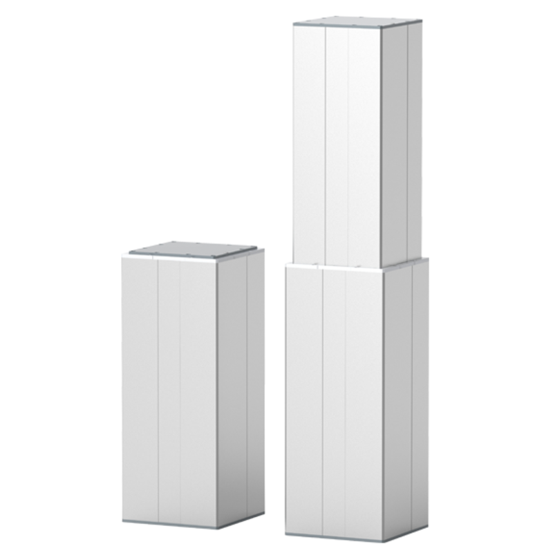
HTB2
A current two-section lifting column reference for industrial vertical-motion projects.
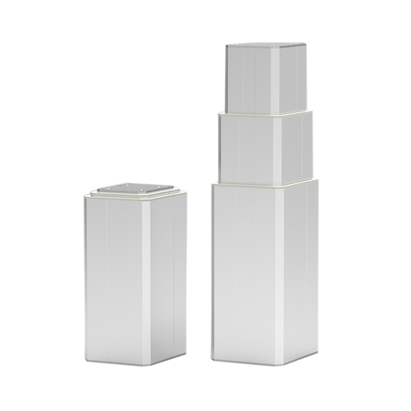
HTB3
A current three-section telescopic lifting column reference where additional travel-to-closed-height ratio is required.
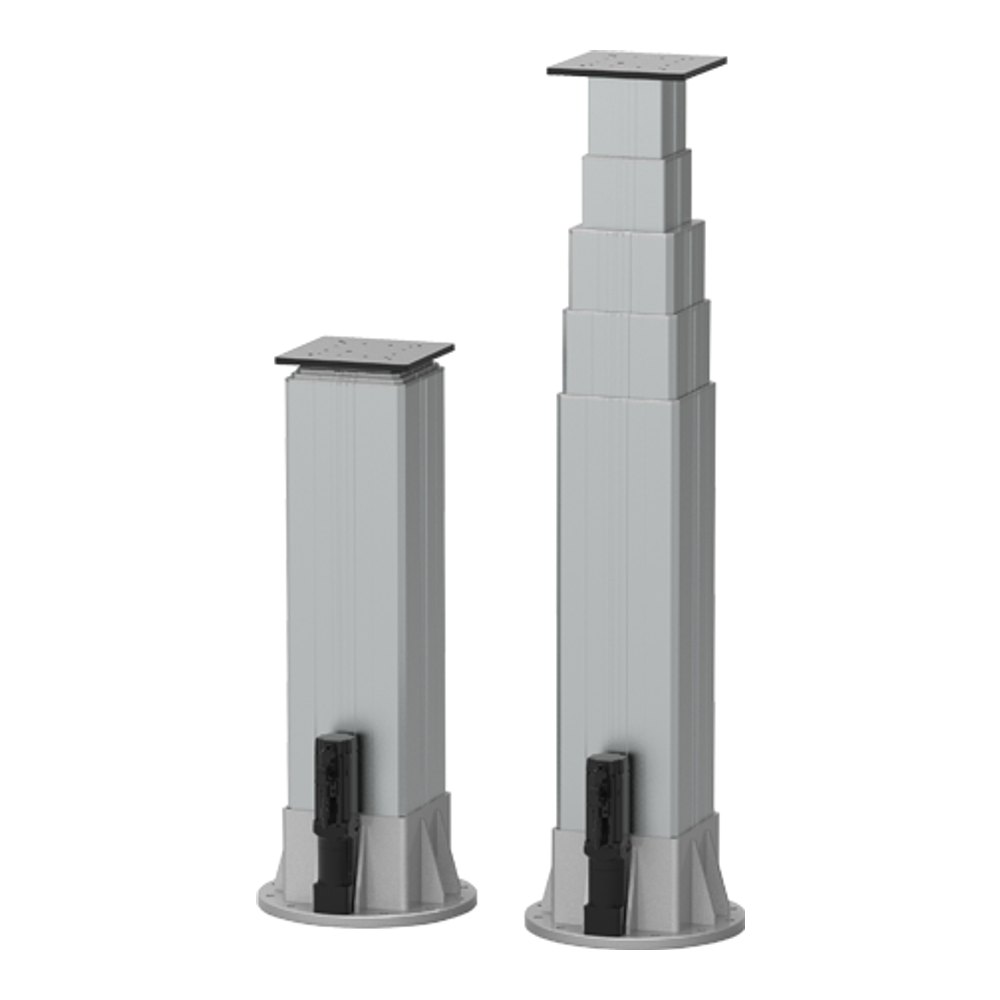
HTD5
A current five-section lifting mast reference for long-travel vertical deployment concepts.
Information required for an engineering review
- Complete installation and payload drawing
- Required travel, retracted height, and extended height
- Moving mass and center-of-gravity coordinates
- Speed, acceleration, cycle rate, and duty cycle
- Voltage, command interface, feedback, and synchronization needs
- Mounting plates, frame stiffness, orientation, and cable route
- Temperature, moisture, dust, vibration, and other environmental conditions
- Applicable machine safety and compliance requirements
For a broader engineering workflow, see the electric lifting column selection guide and the current lifting column range.
Discuss a telescopic lifting requirement
The previewed concept is not available for ordering. For a current-project review, send the application drawing and verified parameters through the GEMING contact page; the engineering team can compare the requirement with released products or assess whether custom development is appropriate.