
A mini linear actuator converts motor rotation into controlled push-pull motion where installation space is limited. Choosing one requires more than checking whether it fits: load, stroke, speed, voltage, duty cycle, environmental protection, mounting, and end-of-travel behavior must be evaluated together.
This guide explains those inputs and compares three compact GEMING actuator configurations using published product specifications.
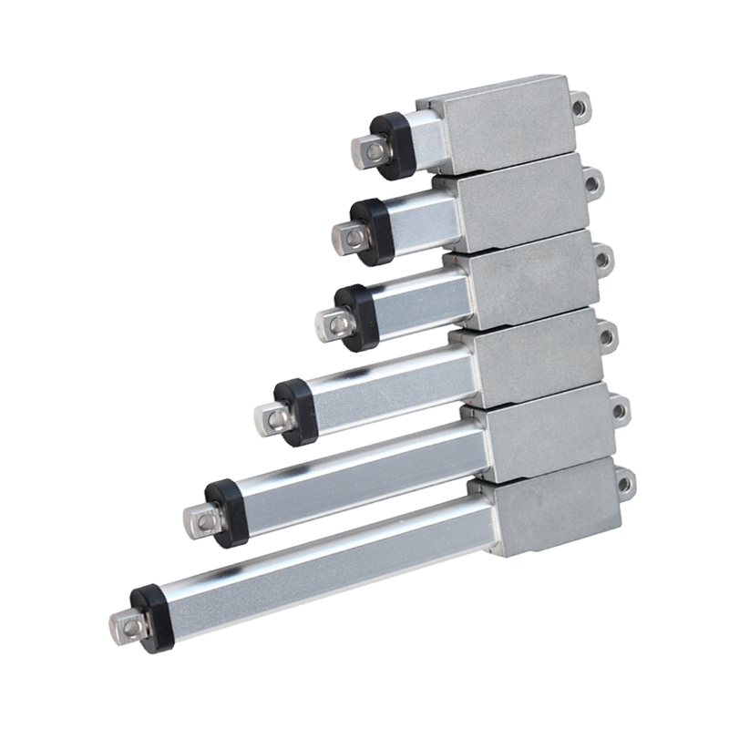
Where a mini linear actuator is useful
Compact actuators suit short-stroke mechanisms in small equipment, adjustment assemblies, access panels, compact fixtures, and other systems where a larger actuator would interfere with the surrounding structure. The actuator still needs external guidance when the mechanism can impose side load or rotation.
Before selecting a model, draw the complete motion path. Check the retracted and extended envelopes, cable bend space, clevis rotation, fastener access, and collision clearance. A small housing does not remove the need for a rigid load path.
Mini linear actuator selection inputs
- Axial load: calculate the force throughout the full mechanism travel, not only at one position.
- Stroke and installed length: confirm required travel as well as the closed and open dimensions.
- Speed under load: use the supplier’s load-speed data for the chosen motor and gear configuration.
- Voltage and controls: match the DC supply, polarity-reversing circuit, current capacity, and required feedback.
- Duty cycle: define run time, rest time, cycles per hour, ambient temperature, and expected service life.
- Environment: select an appropriate IP rating and confirm exposure to dust, moisture, cleaning agents, vibration, and temperature.
- Mounting and side load: align the actuator with the force and provide external guides where the mechanism creates lateral forces.
GEMING compact actuator examples

HTK15 Mini
Compact actuator with an anodized aluminum tube and plastic shell. Published options include 6, 12, and 24 VDC, strokes from 10 to 150 mm, up to 180 N load, and IP54 protection.
HTK15M Mini
Metal-shell compact configuration with published 6, 12, and 24 VDC options, strokes from 10 to 150 mm, up to 180 N load, IP65 protection, and a built-in fixed electrical limit switch.
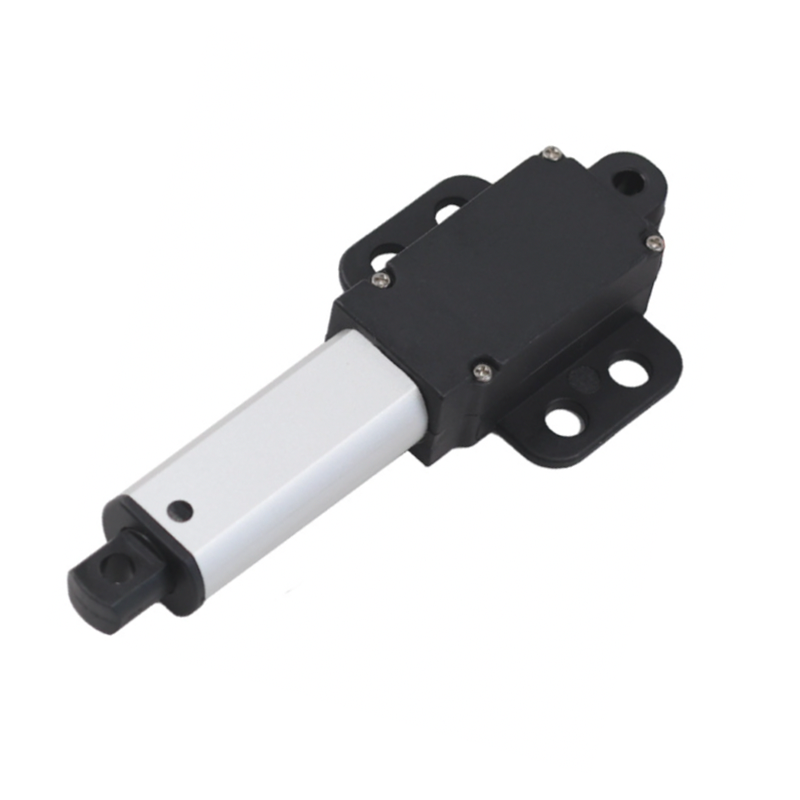
HTK15W Mini
Compact version with mounting support. Published specifications include 6, 12, and 24 VDC, strokes from 10 to 150 mm, up to 180 N load, IP65 protection, and a built-in fixed electrical limit switch.
| Published parameter | HTK15 | HTK15M | HTK15W |
|---|---|---|---|
| Voltage options | 6 / 12 / 24 VDC | 6 / 12 / 24 VDC | 6 / 12 / 24 VDC |
| Stroke options | 10–150 mm | 10–150 mm | 10–150 mm |
| Maximum load | 180 N | 180 N | 180 N |
| Protection class | IP54 | IP65 | IP65 |
| Published duty cycle | 2 min on / 18 min off | 2 min on / 18 min off | 2 min on / 18 min off |
| Housing distinction | Plastic shell | Zinc-alloy shell | Plastic shell with mounting support |
These values are a starting point. Confirm the final configuration, load-speed curve, tolerances, cable details, mounting dimensions, and operating environment against the current model drawing before release.
Product parameter selection example
Consider a compact access panel that requires 45 mm of travel, uses a 24 VDC supply, and operates six times per hour. The mechanism calculation indicates a 70 N peak axial force, but the hinge geometry also creates a changing load angle.
Begin by confirming the worst-case force over the entire travel and applying the machine designer’s approved safety factor. Then compare the 50 mm stroke option, installed dimensions, required speed under load, available current, duty cycle, limit-switch behavior, and the environmental protection level. The panel should be guided by its hinges or dedicated mechanism so the actuator is not used as a side-load bearing.
This example describes a process, not a model approval. Final selection requires the mechanism drawing, force profile, speed, voltage, mounting orientation, cycle rate, and environmental conditions.
Controls, limits, and feedback
A simple two-wire DC actuator is commonly extended and retracted by reversing polarity. The control circuit must be rated for starting and stall current and must define what happens at end of travel, obstruction, power loss, and restart. The three examples above publish built-in, non-adjustable electrical limit switches.
If the machine needs closed-loop positioning or synchronized motion, specify the required feedback and controller before ordering. Do not assume a limit switch provides position measurement. Review the broader electric linear actuator selection guide for system-level sizing inputs.
Information to include in an RFQ
- Application and mechanism drawing
- Required push and pull force over the full travel
- Stroke, closed length, and mounting geometry
- Target speed at the stated load
- Supply voltage and control method
- Run time, rest time, and cycles per hour
- Indoor or outdoor environment and required IP level
- Feedback, connector, cable, and compliance requirements
You can also review the full electric linear actuator range before comparing compact models.
Request a compact actuator review
Send the mechanism drawing, load profile, stroke, speed, duty cycle, voltage, mounting, controls, and environment through the GEMING contact page. The final choice should be verified against the current product drawing and the completed machine.