
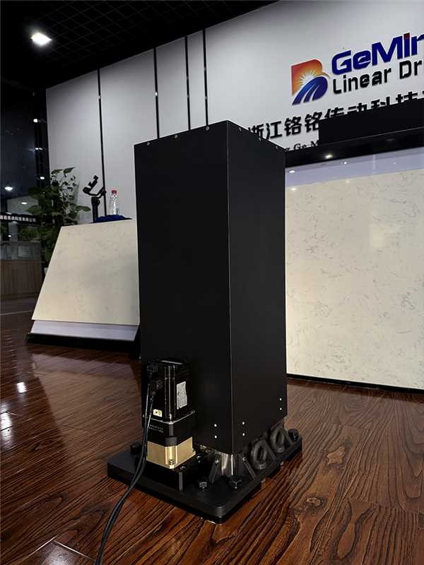
HTG3 lifting column for industrial robots is a practical way to add controlled vertical travel to robot workstations that must handle heavier tooling, long reach, and repeatable positioning. In many automation projects, the robot arm itself is not the only motion system that determines productivity. The vertical axis below the robot, gripper, sensor package, or fixture often decides whether the cell can reach different product heights without changing the whole mechanical layout.
HTG3 is designed for this kind of industrial lifting requirement: a rigid electric lifting column used as a vertical adjustment module for robot stations, handling equipment, inspection devices, and custom automation machines. For heavy-load robot applications, the engineering focus is not only whether the column can move upward and downward. The important questions are load center, eccentric moment, speed, vibration, braking, control response, and how the column behaves after thousands of repeated cycles.
Why industrial robot lifting needs a dedicated column
A robot mounted on a fixed pedestal is simple, but it limits the working envelope. When product height changes, when a robot needs to pick from different container levels, or when a tool must approach from a safer height, a fixed base often forces the integrator to oversize the robot arm or redesign the workstation. A lifting column solves this by adding one controlled vertical degree of freedom under the robot or under the tool assembly.
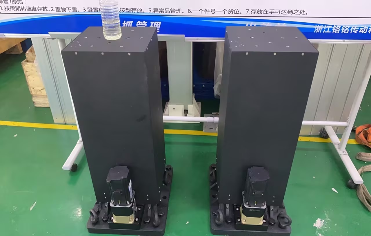
For light-duty applications, a simple actuator may be enough. For heavy tooling or a long eccentric arm, the vertical axis must resist side load and moment load. This is where an industrial lifting column is more suitable than an exposed screw actuator. The column body provides guidance, protects the internal drive, and keeps the moving structure aligned during acceleration and deceleration.
Reference performance window for HTG3 robot applications
For the HTG3 robot lifting application discussed here, the engineering reference condition is a 100 kg application load with an eccentric distance up to 3.5 m. The evaluated speed range is 100-300 mm/s. This range is useful for industrial handling because it gives integrators room to balance cycle time and motion smoothness.
In practical selection, speed should never be viewed alone. A vertical axis running at 300 mm/s with a short, centered load is very different from the same speed with a long offset arm. As speed and offset increase, start-stop shock and vibration become more important. For many 100 kg robot tooling tasks, a middle setting around 150-220 mm/s is usually a safer first commissioning window before the final cycle time is optimized.
Load, speed, and eccentric distance must be checked together
The most common mistake in selecting a robot lifting axis is to ask only for the payload rating. Payload is only one part of the load case. A 100 kg tooling package mounted directly above the column creates a different demand from a 100 kg tool mounted at the end of a long beam. The second case creates higher overturning moment and can increase guide wear, vibration, and base-frame stress.
For robot applications, GeMinG normally reviews the following points before confirming the HTG3 configuration: vertical stroke, retracted height, total moving mass, load center distance, expected travel speed, acceleration profile, duty cycle, mounting direction, brake requirement, and the controller interface. If the robot has cables, air lines, welding hoses, or vacuum tubes, their bending radius and movement path should also be checked at full stroke.
Speed strategy: why S-curve motion matters
Heavy-load lifting columns should not be driven with abrupt starts and stops. A sharp acceleration profile may look fast in a short test, but it adds unnecessary shock to the column, mounting frame, robot base, and tooling. An S-curve acceleration and deceleration profile reduces impact at both ends of the move and helps the robot station maintain stable positioning.
When the target speed is high, the best approach is usually staged commissioning. Start at a lower speed, confirm positioning and vibration, then increase speed step by step while monitoring noise, heat, current, and frame movement. This is especially important when the application combines a 100 kg load with a large eccentric distance.
HTG3 lifting column video
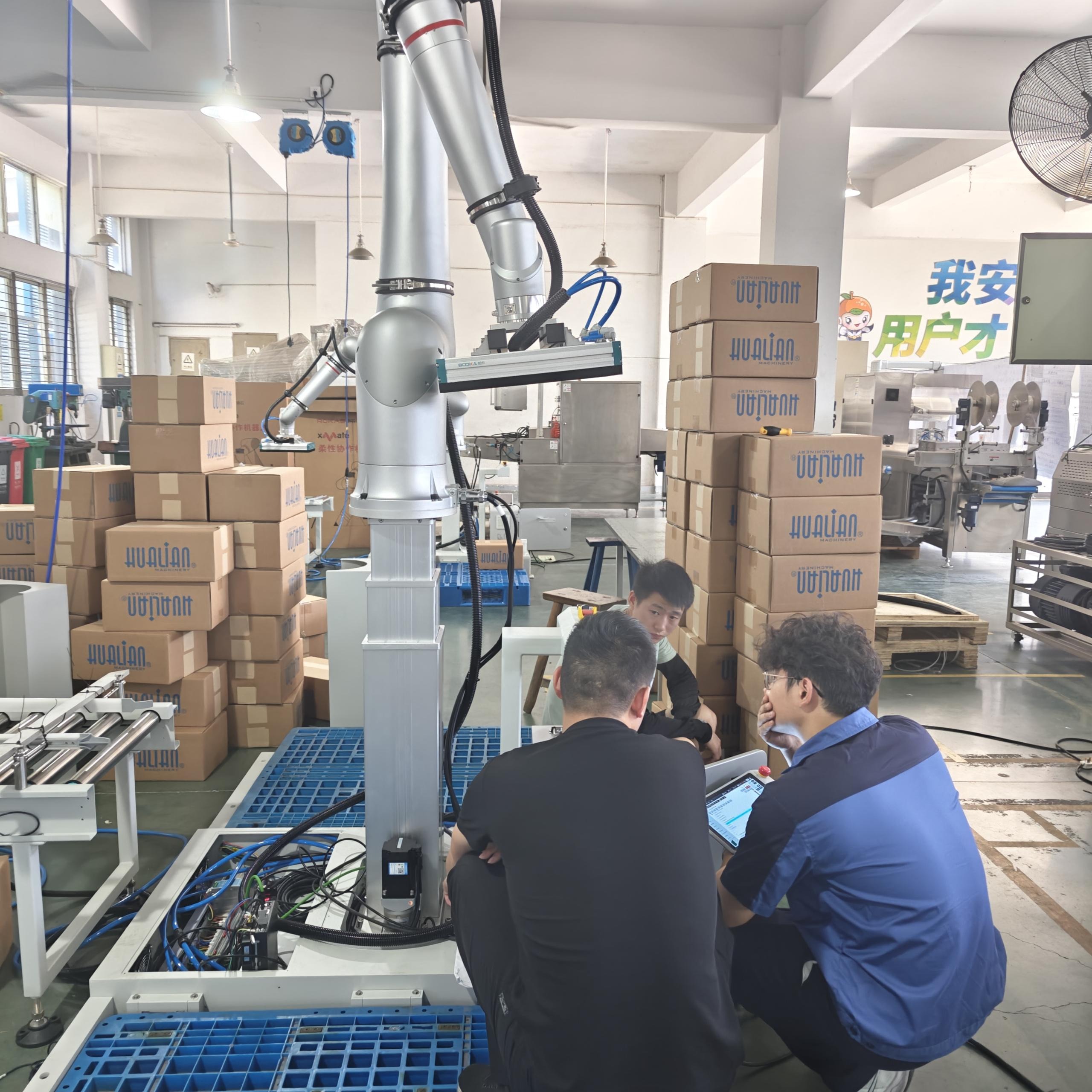
Typical robot and automation scenarios
HTG3 can be used where a robot, tool, or inspection head needs controlled vertical positioning. Typical examples include palletizing and depalletizing stations, machine tending, heavy gripper height adjustment, vision inspection gantries, welding or dispensing equipment, and automated assembly stations with products of different heights.
For integrators comparing different motion methods, GeMinG also provides broader guidance on electric lifting column selection and linear actuator applications. If the project involves collaborative robots or robot workstation layout, the cobot application page is also a useful reference.
Why not use a standard actuator only?
A single linear actuator can generate thrust, but robot lifting is not only a thrust problem. The vertical axis often has to resist lateral force, guide the moving load, protect the drive system, and maintain alignment during repeated high-load cycles. A lifting column integrates the drive and guidance structure into one assembly, which can simplify installation and reduce the need for a separate guide rail system.
For narrow machines or light sensor heads, a compact actuator may still be the right solution. For heavier robot tooling, longer eccentric distance, or high-speed vertical travel, a column structure is usually easier to integrate safely. GeMinG can help compare both options if the customer provides the robot model, payload, stroke, and required cycle time. For general selection principles, see our guide on choosing fully automatic electric lifting columns.
What to prepare before requesting a quotation
To specify an HTG3 lifting column for an industrial robot, prepare the following information: required stroke, minimum and maximum height, static and moving load, load center distance, target speed, expected cycles per hour, mounting orientation, power supply, controller or PLC interface, environmental conditions, and safety requirements. Photos or drawings of the robot base and tooling layout are also helpful.
If the project has strict accuracy requirements, please separate repeatability, absolute positioning accuracy, and allowable vibration. These are different engineering targets. A heavy robot station may meet the required repeatability at a moderate speed, but need additional frame stiffness or reduced acceleration to meet the vibration target at higher speed.
Conclusion
HTG3 gives industrial robot integrators a practical vertical motion module for heavy-load applications. When selected correctly, it can expand robot working height, reduce fixture changes, improve workstation flexibility, and support stable motion under demanding load cases. The key is to evaluate the full operating condition: payload, eccentric distance, speed, acceleration, duty cycle, frame stiffness, and control method.
For a project review, send GeMinG the robot layout and motion requirements. Our engineering team can recommend a lifting column configuration, motor and control option, mounting approach, and safety strategy based on the actual application.
FAQ
Can HTG3 lift a robot directly?
It can be used as a vertical axis for robot stations when the load, moment, stroke, and mounting structure are within the confirmed design range. The final configuration should be checked against the actual robot and tooling layout.
Is 300 mm/s always recommended?
No. 300 mm/s may be possible in some configurations, but heavy loads and large eccentric distances usually require lower acceleration, stronger mounting, and vibration verification. Many projects start testing around 150-220 mm/s.
What information is needed to select the column?
Stroke, total load, load center distance, speed, duty cycle, controller interface, installation space, and safety requirements are the most important starting points.