
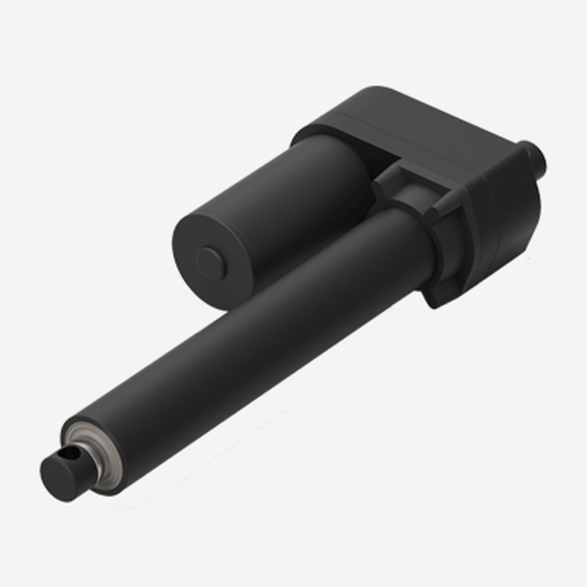
A linear actuator is a device that moves a load in a straight line. In an electric linear actuator, a motor usually turns a lead screw or ball screw; a nut travels along that screw and drives an extension tube, carriage, or guided stage.
Engineers use linear actuators when a machine must lift, push, pull, tilt, open, close, clamp, or position a component with controlled stroke. The correct actuator is selected from load, speed, stroke, duty cycle, mounting, control, and environment—not from force alone.

How does a linear actuator work?
The energy source and transmission method vary, but every linear actuator produces motion along one axis. A typical electric screw-driven actuator follows this sequence:
- The controller supplies power and a direction command to the motor.
- The motor rotates directly or through a gearbox.
- The gearbox turns a lead screw or ball screw.
- A mating nut travels along the screw because the nut is prevented from rotating.
- The moving nut drives an extension tube or carriage to push or pull the load.
- Limit switches, current sensing, a potentiometer, Hall sensors, or an encoder may stop or report the position.
A brake or self-locking transmission may help hold a load when power is removed. Holding behavior must be confirmed for the selected mechanism, load direction, and safety requirement.
What are industrial linear actuators?
Industrial linear actuators are linear-motion devices designed to move, position, or hold loads in machinery and automation equipment. Compared with light-duty adjustment products, an industrial actuator is normally specified against the machine’s actual force, stroke, speed, duty cycle, mounting geometry, feedback, control interface, and operating environment.
Typical duties include opening guards and access panels, positioning fixtures, moving gates or diverters, adjusting machine modules, and operating auxiliary axes. The actuator should usually carry axial push-pull load while the machine structure or an external guide controls side load and bending moment.
For an industrial application, document the complete motion profile rather than selecting from peak force alone. Confirm running and holding loads, cycles per hour, ambient temperature, required ingress protection, mounting-pin loads, end-of-travel protection, feedback resolution, and the machine’s safe behavior after a fault or loss of power. See GEMING’s industrial automation application area and electric linear actuator range for relevant product formats.
Main types of linear actuators
Electric linear actuators
Electric actuators use a motor and mechanical transmission. They are well suited to programmable equipment because speed, direction, end positions, and feedback can be integrated with a control system. They also avoid the pump, valves, and fluid lines required by hydraulic systems.
Pneumatic cylinders
Pneumatic actuators use compressed air to move a piston. They can provide fast, repetitive motion with simple hardware, but accurate intermediate positioning and constant low-speed motion may require additional controls.
Hydraulic cylinders
Hydraulic actuators use pressurized fluid and are often considered when very high force density is required. The complete system includes pumps, valves, hoses, seals, and fluid management.
Mechanical and manual actuators
Hand screws, jacks, cams, and rack-and-pinion mechanisms can also create linear movement. They may be appropriate when adjustment is infrequent or automation is unnecessary.
Core parts of an electric linear actuator
- Motor: provides rotary power; common options include brushed DC, brushless DC, and AC motors.
- Gearbox: changes the speed-torque relationship and can reduce the actuator package size.
- Lead screw or ball screw: converts rotation into linear travel.
- Nut and extension tube: transfer the screw motion to the external load.
- Housing, bearings, and seals: support the transmission and protect internal parts.
- End limits and feedback: stop travel or report position, speed, or direction to the controller.
- Mounting interfaces: connect the actuator to the fixed frame and moving component.
Linear actuator selection parameters
Start with the actual machine geometry and motion profile. A useful specification includes:
- Load: required push and pull force, including gravity, friction, acceleration, and external process forces.
- Stroke: usable linear travel plus any required end clearance.
- Speed: target travel speed under the real load, not only at no load.
- Duty cycle: running time, rest time, cycles per hour, and ambient temperature.
- Mounting geometry: pivot locations, side loading, angular change, and available retracted length.
- Holding requirement: behavior at rest and after power loss.
- Power and controls: voltage, current, direction command, feedback, synchronization, and fault handling.
- Environment: dust, water, cleaning chemicals, corrosion, vibration, and temperature.
- Safety: pinch points, overload, travel limits, emergency stop, guarding, and risk-reduction measures.
Product parameter selection example
Consider a hinged access lid with a mass of 35 kg. The actuator does not lift the lid at its center of gravity; it pushes through a linkage. Required actuator force therefore depends on the lid weight, hinge-to-center-of-gravity distance, actuator attachment points, and the changing angle through the complete stroke.
- Draw the closed, mid-stroke, and open positions with all pivot coordinates.
- Calculate the gravity moment about the hinge at each position.
- Convert that moment into actuator force using the perpendicular distance from the actuator line of action to the hinge.
- Check the position with the smallest effective lever arm; it often requires the highest actuator force.
- Add the approved allowances for friction, acceleration, wind or process load, manufacturing tolerance, and safety.
- Verify stroke, closed length, speed under load, duty cycle, mounting-pin loads, column strength, end limits, and load holding.
This example explains the process and is not a model recommendation. The linear actuator force calculator can support the geometry check, but final selection still requires the complete mechanism drawing and operating conditions.
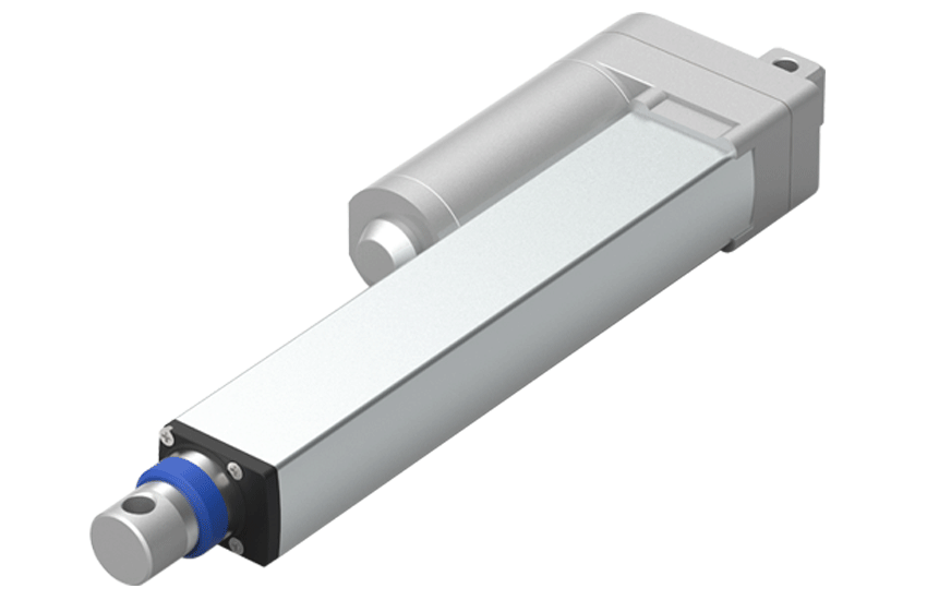
Where are linear actuators used?
- Industrial automation: gates, guards, diverters, fixtures, inspection devices, and material-handling equipment.
- Mobile equipment: access panels, hatches, covers, steps, and auxiliary mechanisms.
- Medical and laboratory equipment: adjustable platforms, instrument positioning, and access mechanisms, subject to applicable system requirements.
- Robotics: tool positioning, auxiliary axes, and height adjustment. Guided cobot lifting columns are often more suitable when the complete robot must move vertically.
- Ergonomic equipment: adjustable desks, workstations, consoles, and operator platforms.
Linear actuator vs lifting column
A rod-style linear actuator produces push-pull motion and normally relies on the machine structure or linkage to control side load. An electric lifting column combines linear drive with a guided telescopic structure and is commonly used for vertical platforms or height-adjustable systems.
The right choice depends on the load path and guidance already present in the machine. Review the full range of GEMING linear actuators only after the required force, stroke, speed, duty cycle, controls, and environment are defined.
Frequently asked questions
What is a linear actuator in simple terms?
It is a device that moves something in a straight line instead of rotating it. It can push, pull, lift, lower, open, close, or position a load.
What are industrial linear actuators used for?
They provide controlled straight-line movement in machinery, including guards, gates, fixtures, diverters, access panels, adjustable modules, and auxiliary automation axes. Selection depends on the full load and motion profile, mounting, duty cycle, controls, and environment.
How does an electric linear actuator convert rotary motion?
A motor turns a lead screw or ball screw. A nut travels along the screw and moves an extension tube or carriage.
Can a linear actuator hold a load without power?
Some transmissions are self-locking or include a brake, but holding performance depends on the actuator design, load direction, vibration, wear, and safety requirement. It must be confirmed for the selected model.
What is the difference between stroke and retracted length?
Stroke is the usable travel. Retracted length is the actuator’s end-to-end installation length when fully closed. Both must fit the mechanism geometry.
Why does actuator speed decrease as force increases?
Motor power, gearing, screw lead, efficiency, voltage, and thermal limits create a force-speed tradeoff. Use the model’s load-speed data rather than assuming the no-load speed.
Does a linear actuator need external guides?
Use external guidance when the moving load can apply side force, bending moment, or rotation that the actuator is not designed to carry.
Prepare an actuator specification
Send the load, mechanism drawing, stroke, speed, duty cycle, mounting points, voltage, controls, feedback, and environment through the GEMING contact page for a technical review.
For system architecture decisions, compare electric and hydraulic linear actuators, including control, maintenance, force, duty cycle and environmental considerations.