
Introduction
To choose an electric lifting column, start with the real load, required stroke, closed length, stability, duty cycle, control method, and operating environment. Rated load alone is not enough.
A column can meet its rated load and still be unsuitable for the machine. Off-center loads, poor guidance, an excessive stroke, or the wrong synchronization method can reduce stability and service life.
This guide explains how to choose a lifting column step by step for medical equipment, industrial workstations, smart furniture, and other height-adjustable systems.
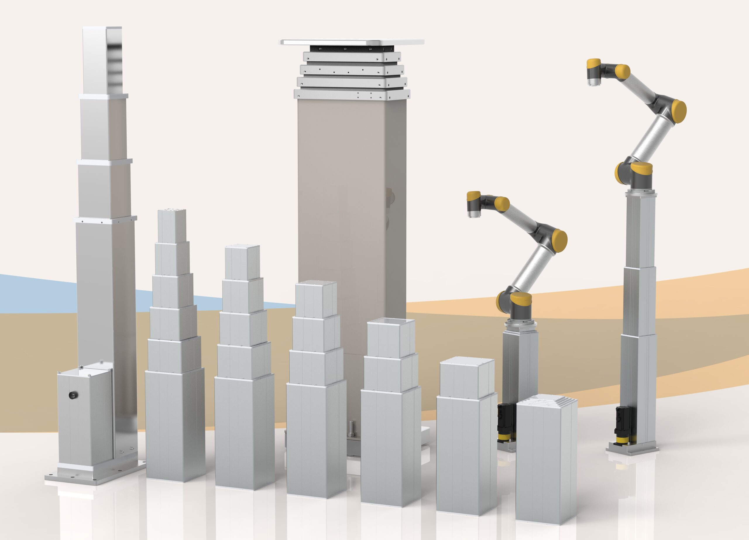
1. Beyond Rated Load: Evaluating Real-World Forces
The first step is to define how much weight the column needs to lift. However, looking exclusively at the static load value listed on a datasheet is a critical mistake.
To ensure long-term reliability, you must evaluate the entire force profile:
- Total System Mass: The dead weight of the structure plus the maximum variable payload.
- Dynamic vs. Static Load: Dynamic load is the force applied during movement; static load is the holding capacity when stationary.
- Eccentric (Off-Center) Loading: If the load is not perfectly centered over the column’s vertical axis, it creates a bending moment (torque) on the internal guiding profiles.
- Multi-Column Distribution: If a system carries 200 kg and uses two columns, it does not mean each column handles exactly 100 kg. If the load shifts or is unevenly distributed, one column may carry up to 70% or more of the total force.
Engineering note: Do not select a column at its theoretical limit. Define a safety margin from the actual load case, motion profile, expected impacts, mounting structure, and applicable machine-safety requirements. A universal percentage is not suitable for every project.
2. Define Stroke and Retracted Length: 2-Stage vs. Multi-Stage Lifting Columns
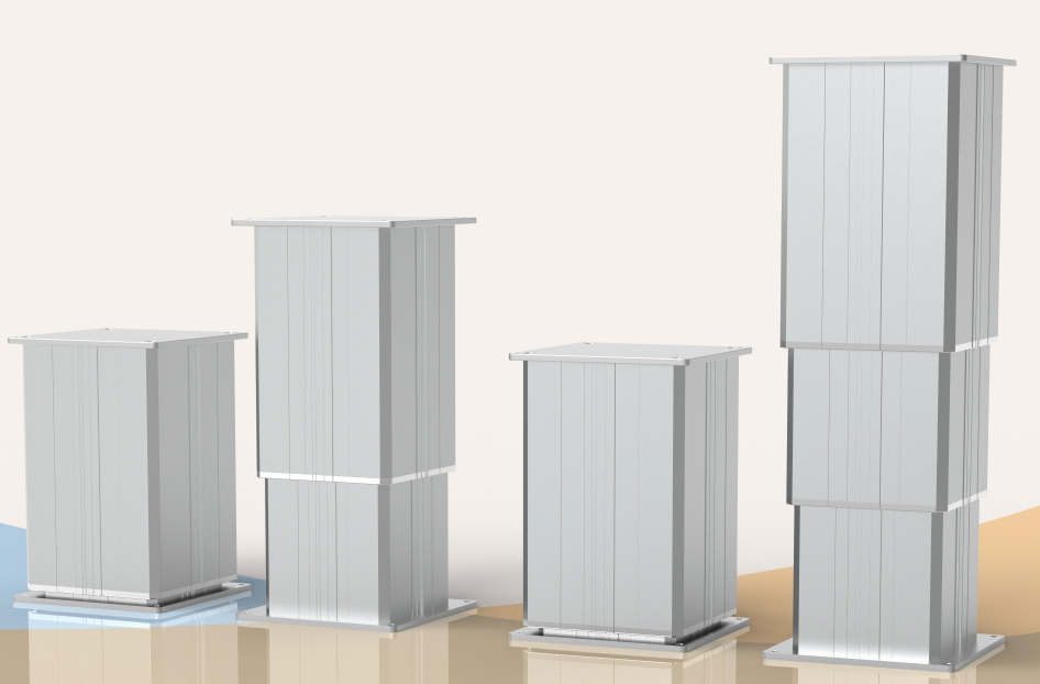
Stroke is the travel distance the column needs to move. This is one of the most important selection parameters.
Ask these questions:
- What is the absolute minimum allowable height of the system?
- What is the maximum required operational height?
- Is installation space limited when the column is fully retracted?
Deciding Between 2-Stage and Multi-Stage Telescopic Columns:
Choose a 2-Stage Lifting Column if: Your project has flexible installation space, requires a moderate stroke, and is highly cost-sensitive. A 2-stage column uses a single moving profile nested inside a static base. It offers excellent stability and cost efficiency but requires a much taller retracted height to achieve a long stroke.
Choose a Multi-Stage Lifting Column (3-Stage and Beyond) if: Compact installation space is critical, but a massive vertical travel range is required. By nesting multiple moving profiles inside one another, multi-stage columns achieve an aggressive stroke-to-retracted-length ratio. This allows the system to drop incredibly low to the ground while still reaching extended working heights.
Engineering and budget note: A three-stage column often provides a practical balance between stroke and closed length. Four- and five-stage designs require more nested profiles, guides, and internal cable management.
These extra interfaces increase manufacturing complexity and cost. Use additional stages only when the installation envelope requires them.
Furthermore, to guarantee uniform movement, manage shifting centers of gravity, and maintain constant torque across so many overlapping profiles, columns with more than 3 stages default to adapting with high-precision servo motors rather than standard DC drives. This ensures the absolute synchronization and closed-loop feedback required for ultra-low tolerance industrial and robotic applications.
For a closer look at the trade-offs between stage count, retracted height, profile overlap, bending stiffness, and validation, see the telescopic lifting column design preview. The preview documents an unreleased concept and should not be treated as a purchasable model specification.
3. Balance Speed, Load, and Application Needs
Speed affects both user experience and work efficiency.
For example:
- In medical or care equipment, movement should be smooth and safe.
- In office or furniture systems, moderate speed is usually acceptable.
- In industrial automation, speed may directly affect cycle time and productivity.
Speed directly impacts both user experience and overall system cycle time, but it cannot be evaluated in isolation. In linear motion engineering, speed and load capacity are inversely proportional given a fixed motor size; higher speeds typically mean lower lifting capacities.
4. Evaluate Structural Stability and Eccentric Loads/Bending Moments
Lifting columns are chosen over standard linear actuators primarily because their nested aluminum or steel profiles provide integrated guidance and structural stability. They act as a load-bearing column and an actuator all in one.
However, as a column extends, its susceptibility to bending moments increases. You must calculate:
- Installation base width
- Center of gravity of the moving structure
- Extended height
- Side load and bending moment
- Whether the system uses one column or multiple columns
Engineering insight: Tall-stroke systems need more than motor-force calculations. As extension increases, profile overlap, guide clearance, mounting rigidity, and the payload’s center of gravity become more important.
Review the full extended structure for bending, vibration, and binding risk before choosing the column.
5. Single vs. Multi-Column Systems: The Synchronization Factor
When a project requires two or more columns to lift a single, rigid platform, the control system ceases to be an afterthought—it becomes the heart of the solution.
Multi-column integration introduces complex engineering challenges:
- Synchronization Accuracy: If one column moves even slightly faster than the other, the platform will tilt, causing structural binding, mechanical stress, or safety hazards.
- Feedback Logic: The system must utilize advanced control boxes paired with Hall sensors, CAN bus communication, or other signal outputs to monitor individual column positioning in real-time.
6. Match Environmental Constraints to Material Specifications
A pristine, climate-controlled indoor environment demands a completely different structural design than a harsh industrial factory floor or an outdoor engineering site.
Ensure your column’s specifications align with these environmental variables:
- Ingress Protection (IP Rating): Do you need protection against fine dust, splashing water, or high-pressure washdowns (e.g., IP54 or IP67)?
- Duty Cycle: Is the system operating continuously, or does it follow a standard intermittent duty cycle (e.g., 10%, meaning 2 minutes of continuous operation followed by 18 minutes of rest)?
- Acoustic Limits: Does the application require ultra-low noise levels (under 50 dB) for clinical settings?
☢️ Case Study Focus: For our specialized nuclear power plant engineering projects—which began rigorous testing in 2020 and have achieved stable, multi-year operation—the columns require custom heavy-duty sealing, specialized coatings, and robust internal gearing engineered to withstand rigorous continuous performance with zero tolerance for failure.
7. 2-stage vs 3-stage lifting column: quick comparison
| Engineering Factor | 2-Stage Lifting Column | 3-Stage Lifting Column | Multi-Stage Lifting Column (4+ Stages) |
| Profile Structure | 2 nested sections (1 extension stage) | 3 nested sections (2 extension stages) | 4 to 5+ nested sections (3+ extension stages) |
| Retracted Space | Requires maximum vertical clearance when closed. | Compact; excellent balance of closed height to travel. | Ultra-compact; fits into minimal vertical clearance envelopes. |
| Stroke Capability | Moderate travel range. | Long travel range relative to closed height. | Maximum travel range with highly aggressive telescoping ratio. |
| Relative Cost | Baseline / Most cost-effective. | Moderate / Standard premium. | Exponentially higher / Premium due to hyper-strict tolerance engineering. |
| Default Motor Drive | Standard DC / Brushed motors. | Optional Brush, Brushless or Servo motor. | High-precision Servo Motors (closed-loop control for uniform torque). |
| Typical Use Cases | Standard industrial workstations, assembly lines, basic height-adjustable furniture. | Mobile medical carts, ergonomic touch tables, collaborative robot (cobot) pedestals. | Ultra-low profile automated guided vehicles (AGVs/AMRs), specialized heavy aerospace rigs, advanced custom robotics. |
8. Common Engineering Mistakes to Avoid
Choosing only by maximum load
Rated load is important, but it is not enough. Real applications also involve side force, instability, and movement conditions.
Ignoring closed length
A column may provide enough stroke but still not fit the actual structure.
Overlooking control and synchronization
In multi-column systems, the controller and control logic are part of the solution.
Not considering end-use conditions
Noise, duty cycle, moisture, and installation layout all affect long-term performance.
9. RFQ Checklist: What to Prepare for a Rapid Technical Quotation
To help our engineering team recommend the most precise, cost-effective, and long-lasting linear motion solution for your project, please have the following parameters ready:
- [ ] Application Type: (e.g., AGV/AMR platform, cobot lift, medical bed, industrial desk)
- [ ] Dynamic & Static Load Requirements: (in kg or Newtons)
- [ ] Target Bending Moment / Side Load: (if applicable)
- [ ] Required Stroke Distance: (in mm)
- [ ] Maximum Allowable Retracted Length: (in mm)
- [ ] Number of Columns per System: (Single, 2-way split, 4-way sync, etc.)
- [ ] Target Operating Speed: (mm/s at full load)
- [ ] Input Voltage & Control Preferences: (e.g., 24VDC, 110V/220VAC, Hall sensor feedback, CAN bus)
- [ ] Environmental Constraints: (IP rating requirements, noise limits, duty cycle)
The clearer the input parameters, the faster and more accurately the solution can be recommended.
Conclusion of How to Choose Electric Lifting Column
Choosing the right lifting column is a system decision, not a single-parameter decision. Load, stroke, speed, stability, installation space, and control requirements must all be considered together.
If you are working on a new project or replacing an existing lifting system, preparing the right technical information at the beginning can save a lot of time during selection and testing.
Partner With Linear Motion Experts
Need a custom engineering evaluation for a complex project? Our technical team specializes in developing high-performance, synchronized, and environmentally tailored lifting systems.
[Contact Our Technical Sales Team] with your layout drawings, load dynamics, and application environment for a detailed, data-driven recommendation.
Technical FAQ: Selecting Electric Lifting Columns for OEM & Industrial Applications
Related Lifting Column Applications
Application-specific planning is covered in the cobot lifting column guide and the medical equipment lifting column guide. Both examples still require verification against the final load, offset, stroke, mounting, duty cycle, controls and safety requirements.
Calculate the bending moment from the payload force and its horizontal offset. Provide the center-of-gravity position, dynamic lateral forces, and mounting layout so the supplier can check profile size, guide overlap, and external support needs.
A servo drive may be suitable when the application requires smooth low-speed motion, repeatable positioning, or coordinated multi-axis control. The decision should consider load, speed, stage count, duty cycle, and allowable position error rather than stage count alone.
The controller compares feedback from Hall sensors, encoders, or servo drives and corrects relative position during movement. The system should stop when position deviation, motor current, or obstruction signals exceed validated limits. The final tolerance must be confirmed on the complete platform.
Use the duty-cycle rating in the selected model's datasheet and verify it at the expected load and ambient temperature. For frequent motion, provide moves per hour, running time, rest time, speed, and required service life. Higher-duty systems may require a BLDC or servo drive, improved cooling, or a more efficient screw mechanism.
Load holding depends on screw type, gear ratio, load direction, and brake design. A ball-screw column may need a power-off brake or another holding device, while a trapezoidal screw's self-locking behavior must still be verified under the actual load. The finished machine should be tested for power-loss and brake-failure conditions.