
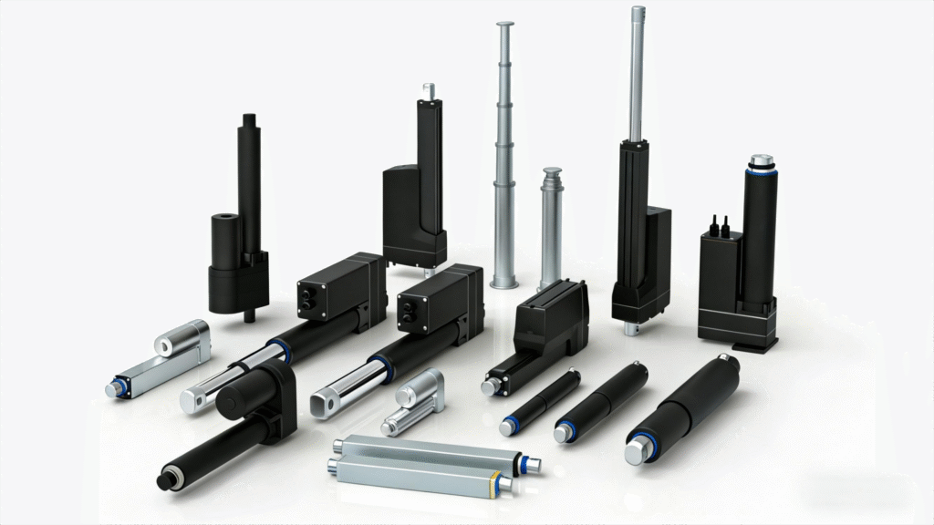
Selecting an electric linear actuator requires more than matching thrust and stroke. OEM teams must also check speed, duty cycle, mounting, and side load. A wrong choice can cause binding, overheating, or early failure.
Self-supporting lifting columns include structural guidance for bending loads. In contrast, electric linear actuators and cylinders are primarily designed for pure axial thrust.
This guide provides a step-by-step selection process. It covers industrial automation, robotics, material handling, and heavy-duty machinery.
Engineering Geometry Calculators
Actuator force depends on the mechanism geometry as well as the lifted load. Use the scissor lift actuator force calculator for crossed-arm lift mechanisms. Use the third-class lever actuator calculator when the actuator sits between the pivot and the load. These tools support an early comparison. Final sizing must also check dynamic load, friction, duty cycle, mounting strength, and safety factor.
1. Define the Load
The foundation of actuator selection is defining the load. However, a single “maximum load” value is insufficient for proper component sizing. You must analyze the complete force-over-time profile:
- Thrust vs. Pull Forces: Does the actuator experience the same load when extending (pushing) as it does when retracting (pulling)? Many mechanical linkages place highly asymmetric forces on the drive rod.
- Dynamic vs. Static Load: Dynamic load is the force needed during motion. Static load is the force held when the motor stops.
- Peak Shock Loads: In applications like pressing, stamping, or rugged outdoor deployment, the actuator may experience sudden, high-impact forces. A severe shock can damage the gears or bend the screw.
💡 Engineering check: Calculate the Root Mean Square (RMS) load across the full cycle. Size the motor and screw from the continuous RMS load to avoid thermal overload. Then confirm that the actuator can withstand the maximum peak shock load.
For high-force equipment, continue with the heavy duty linear actuator selection guide. It compares published 20–65 kN configurations and explains how to review force, speed, stroke, duty cycle, mounting, IP rating, feedback, and controls together.
2. Check Side Load and Buckling
A common cause of early failure is unintended side load. Standard industrial actuators and cylinders are designed to push and pull strictly along their longitudinal axis.
The Problem with Lateral Force:
Side force presses the rod against its bushings and seals. This can wear the seals and let dust or water enter. It can also bend the screw or damage the tube.
Critical Sizing Factors:
- External Guidance: Side loads can occur when an actuator moves a heavy hinged panel. Use external guide rails, linear bearings, or guide rods to isolate the actuator from these loads.
- Euler’s Buckling Limit: For long-stroke applications (typically over 500 mm) under heavy compression (thrust) loads, the extending rod acts as a structural column. Check the critical buckling limit against stroke, rod diameter, and force. Exceeding this limit can bend or break the rod.
3. Choose the Screw Type
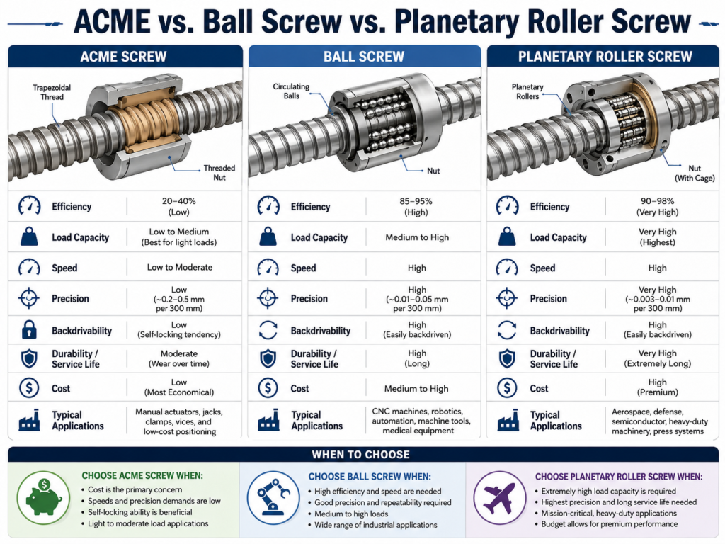
1. ACME / Trapezoidal Lead Screws (Sliding Friction)
- How it works: Uses a threaded nut sliding along a threaded screw.
- Characteristics: Low efficiency (typically 30%–40%), which means significant energy is lost as heat. However, high friction provides excellent natural self-locking capability, meaning it will not back-drive when power is removed.
- Best for: Low duty-cycle, cost-sensitive applications where a holding brake is undesirable.
2. Ball Screws (Rolling Friction)
- How it works: Utilizes recirculating ball bearings between the nut and the screw.
- Characteristics: High mechanical efficiency (90%+), minimal friction, long predictable lifecycles, and capability for high speeds and continuous cycles. However, due to low friction, ball screws can easily back-drive under load, requiring an electromagnetic motor brake to hold position.
- Best for: Industrial automation, high-speed applications, precise positioning, and high duty cycles.
3. Planetary Roller Screws (Line Contact Rolling)
- How it works: Threaded rollers rotate around the main screw. They provide several contact lines.
- Characteristics: Roller screws can provide high load capacity and stiffness. Their life still depends on load, speed, lubrication, and alignment.
- Best for: Heavy-duty electric cylinders replacing high-pressure hydraulics, aerospace actuators, and heavy pressing/stamping machinery.
4. Choose the Motor and Controls
The choice of motor drive directly controls the intelligence, repeatability, and duty cycle limits of the electric cylinder.
- Brushed DC Motors: Excellent for simple, cost-effective, point-to-point motion with low duty cycles ( 10%~25%). Position feedback is typically limited to basic mechanical limit switches, internal Hall sensors or potentiometer.
- Brushless DC (BLDC) Motors: Removes the wear-prone carbon brushes, allowing for significantly higher duty cycles, faster speeds, and longer operational lifecycles.
- Servo Motors (Closed-Loop Servo Cylinders): The gold standard for precision industrial automation. A servo system can control speed, position, and force. Encoder feedback supports repeatable motion. Confirm the real duty rating with the motor and drive supplier.
5. Choose the Mounting Layout
Choose a layout that fits the available space and load path.
Physical Orientation:
- Inline Configuration: The motor is mounted directly behind the actuator cylinder housing, creating a long, slim profile. Ideal for narrow spaces.
- Parallel (Foldback) Configuration: The motor sits beside the actuator body. A belt or gear transfers power. This significantly reduces the total longitudinal length of the unit.
Mounting Interfaces:
The mounts must keep the actuator aligned with the load:
- Clevis / Pin Mounts: Features rear and rod-end holes secured by pins. The pins let the actuator pivot as it moves. This helps prevent binding.
- Trunnion / Flange Mounts: These mounts attach directly to the cylinder body. They suit rigid, high-force layouts when the structure carries the reaction load.
- Customization: You can also send us the drawing with your own design for customization mounting.
When the installation envelope is the primary constraint, use the mini linear actuator selection guide to compare compact stroke, voltage, duty-cycle, IP-rating, mounting, and control requirements.
6. Check the Environment
Dust, water, and washdown chemicals can damage seals. The exposed rod can collect dirt. Retraction may pull that dirt toward the rod seal.
- Ingress Protection (IP Rating): Standard indoor factory automation typically requires IP54 or IP65. Extreme outdoor deployment (agricultural machinery, solar trackers) requires IP66 or IP67.
- Hygienic & Food-Grade (IP69K): Food and pharmaceutical lines often need smooth, crevice-free surfaces. Use suitable stainless steel or protected aluminum for chemical washdowns. Confirm resistance to pressure, temperature, ingress, and corrosion.
7. Product Parameter Selection Example
Consider a guided machine axis that must move a 300 kg load through a 400 mm stroke in 12 seconds. The actuator carries axial force only because external rails support side loads.
- Moving mass: 300 kg
- Stroke: 400 mm
- Target speed: about 33 mm/s
- Duty cycle: 20%, subject to the real cycle profile
- Environment: indoor industrial use with dust protection
Start with the static load: 300 × 9.81 = 2,943 N. Add acceleration, friction, and the required safety margin before selecting the rated thrust. Then check buckling at full extension, motor power, brake requirements, mounting-pin strength, limit switches, and thermal duty. This example explains the process; it does not select a product model.
8. Prepare These RFQ Inputs
To minimize engineering lead times and ensure an accurate application evaluation, please prepare the following parameters for our technical team:
- [ ] Primary Motion Type: (e.g., Pushing, pulling, lifting, pressing, articulating linkage)
- [ ] Dynamic Load (Normal Operating Force): (in Newtons or kg)
- [ ] Maximum Peak or Shock Load: (in Newtons or kg)
- [ ] Is there any Lateral / Side Load? (Yes/No, specify force value and external guidance mechanism if present)
- [ ] Required Stroke Length: (in mm)
- [ ] Target Velocity / Cycle Speed: (in mm/s, or total time allowed per stroke)
- [ ] Daily Duty Cycle: (Cycles per minute/hour, or percentage of run-time vs. rest-time)
- [ ] Required Positioning Repeatability: (in mm or microns)
- [ ] Motor Input Preferences: (e.g., 12/24/48VDC brush motor, 3-Phase 220/400VAC, Stepper, Brushless, Servo)
- [ ] Mounting Profile Requirement: (Inline vs. Parallel; Rear Clevis, Front Flange, Trunnion)
- [ ] Operating Environment: (Temperature limits, dust/moisture exposure, washdown chemicals, IP rating requirement)
Technical FAQ: Selecting Electric Linear Actuators
Q1: When is an electric cylinder a good choice?
A: Choose an electric cylinder when the machine needs clean operation and controlled positioning. A hydraulic system needs pumps, valves, hoses, and fluid service. It may also leak. A servo cylinder can control position, speed, and force. It does not need hydraulic fluid. Compare both systems against the real load and duty.
Q2: When is an ACME screw useful?
A: The primary reasons are cost efficiency and self-locking safety. ACME screws are significantly simpler and more economical to manufacture. Furthermore, their high mechanical friction creates a natural mechanical lock. An ACME screw can suit equipment that moves only a few times each day. Its friction can help hold a load when power is off. Confirm the actual self-locking behavior for the selected lead angle, load, and vibration.
Q3: Can I mount an electric linear actuator in any orientation?
A: Yes, electric actuators can operate vertically, horizontally, or at any angle. However, the orientation alters the force profile. A vertical axis must lift the load and hold it at rest. A horizontal axis mainly works against friction and acceleration.
Q4: How is ball screw life estimated?
A: Ball screw and roller screw life is commonly estimated with a modified bearing-life method. The $L_{10}$ calculation can be expressed in revolutions or travel distance. The estimate uses load, speed, travel per cycle, and operating conditions. Provide the duty cycle and load profile for a project review.
Engineer Your Next Motion Solution With Us
You may be replacing a pneumatic cylinder or developing a high-force assembly axis. Our technical team can review the load case and propose a suitable linear drive configuration.
Contact our engineering team and send the drawing, load, stroke, speed, duty cycle, and environment.