
A heavy duty linear actuator must move the required load safely throughout the complete mechanism cycle—not merely produce a large catalogue force number. Force, speed, stroke, duty cycle, mounting, side load, braking, controls, feedback, and environmental protection must be evaluated as one system.
This engineering guide compares four published GEMING configurations from 20 kN to 65 kN and explains how an OEM can turn application data into a useful actuator specification.
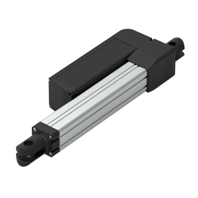
What qualifies as a heavy duty linear actuator?
There is no universal force threshold that makes an actuator “heavy duty.” The term normally describes a combination of high axial force, robust mechanical construction, suitable environmental protection, and controls designed for demanding industrial equipment. A 20 kN actuator can be heavy duty in one machine, while another application may require 50 kN or more.
The useful question is therefore not “Which actuator has the highest load rating?” but “Which configuration meets the force, travel, speed, life, environment, and safety requirements of this mechanism?” Start with a force-versus-position profile and the real operating cycle. Static holding force, dynamic push or pull force, and shock load are different design conditions.
Eight inputs to define before model selection
- Dynamic force: calculate push and pull force over the full travel, including friction, acceleration, mechanism angle, and process load.
- Static holding requirement: state what the mechanism must hold when stopped or without power and whether a separate brake or mechanical support is required.
- Stroke and installed length: confirm travel, closed length, extended envelope, cable clearance, and service access.
- Speed under the stated load: force and speed are linked. A maximum-speed value at a light load does not describe performance at maximum force.
- Duty cycle: specify run time, rest time, cycles per hour, ambient temperature, and expected life.
- Mounting and guidance: keep the actuator aligned with the force. Use external guides to carry side load, bending moment, and rotation.
- Environment: identify dust, water, washdown, corrosion, vibration, temperature, and the required ingress-protection level.
- Controls and feedback: define supply, controller, limit behavior, position feedback, synchronization, communications, emergency stop, and power-loss behavior.
Heavy duty GEMING actuator examples
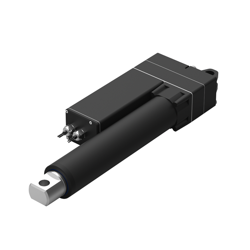
HTL2 — up to 20 kN
Published options include a brushless DC motor, 24 or 48 VDC and 220 VAC, stroke up to 900 mm, IP66 protection, a ball screw, and optional potentiometer, Hall, endpoint, synchronization, independent, or CAN bus control.
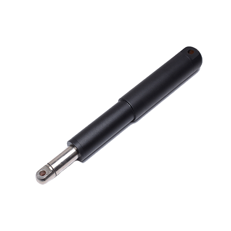
HTK75 — up to 28 kN
This inline configuration publishes 12, 24, 36, and 48 VDC options, stroke up to 900 mm, IP66 protection, Hall feedback as an option, and a 10% duty-cycle statement of 2 minutes on and 18 minutes off.
TF75 — up to 50 kN
Published data includes 48 VDC or 220–380 VAC, 50–2,000 mm stroke, IP66 protection, a built-in brake hold, manual operation during a power outage, and optional synchronization or industrial communications.
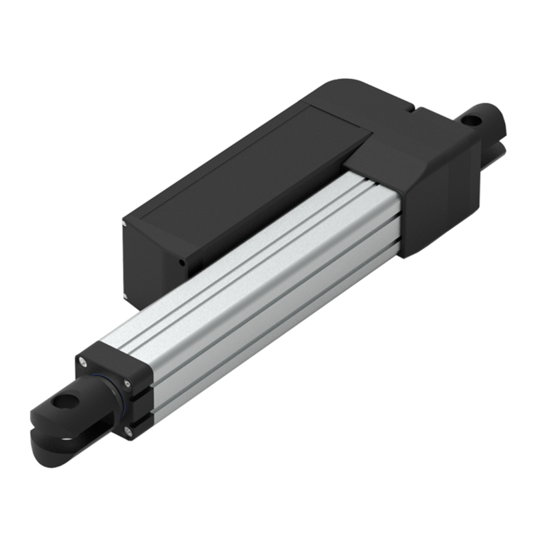
TF93 — up to 65 kN
The higher-force TF93 publishes the same 48 VDC or 220–380 VAC supply families, 50–2,000 mm stroke range, IP66 protection, brake hold, manual operation, and control or communication options.
| Published parameter | HTL2 | HTK75 | TF75 | TF93 |
|---|---|---|---|---|
| Maximum listed load | 20,000 N | 28,000 N | 50,000 N | 65,000 N |
| Stroke | Up to 900 mm | Up to 900 mm | 50–2,000 mm | 50–2,000 mm |
| Voltage families | 24 / 48 VDC; 220 VAC | 12 / 24 / 36 / 48 VDC | 48 VDC; 220–380 VAC | 48 VDC; 220–380 VAC |
| Protection class | IP66 | IP66 | IP66 | IP66 |
| Selected control or feedback options | Potentiometer, Hall, endpoint, synchronization, CAN bus | Hall; compatible GEMING HTT controls | Synchronization, integrated control, CAN, CAT, RS485 | Synchronization, integrated control, CAN, CAT, RS485 |
The table is a first-pass comparison, not a release specification. Confirm the current drawing, exact motor and screw option, load-speed curve, duty rating, tolerances, connector, cable, braking behavior, feedback resolution, and environmental limits for the selected configuration.
Force and speed must be evaluated together
Large force figures can hide a critical trade-off. The TF75 page, for example, publishes 250 mm/s at a 2,000 N load and 8 mm/s at a 30,000 N load. The TF93 publishes 250 mm/s at 2,000 N and 8 mm/s at 50,000 N. These are different operating points, not interchangeable headline specifications.
For a useful review, provide at least two points: the required continuous or peak force and the required speed at that force. If speed changes during the cycle, provide a motion profile. Also state acceleration, deceleration, settling time, and position accuracy where they matter to the machine.
Product parameter selection example
Consider an industrial fixture requiring 750 mm of travel. A mechanism calculation indicates 18 kN peak dynamic push force near one end of travel and 12 kN through the remainder. The target movement time requires 25 mm/s at the 18 kN point. The equipment operates indoors but is exposed to dust and occasional water spray, uses a 48 VDC control architecture, and completes four cycles per hour.
Begin by validating the complete force profile and the machine designer’s approved design margin. HTL2 enters the discussion because its published maximum load is 20 kN and it offers 48 VDC, a stroke up to 900 mm, IP66 protection, and multiple feedback or control options. But the catalogue maximum alone is not approval: the required 25 mm/s must be checked on the correct load-speed curve, and the thermal cycle must be verified for the specified ambient temperature.
The mounting drawing must then confirm closed length, clevis geometry, alignment, cable movement, and maintenance access. External guides should carry lateral forces from the fixture. Finally, verify holding and power-loss behavior, feedback type, controller current, end limits, braking or mechanical support, compliance requirements, and validation testing on the completed machine.
Mounting, side load, and structural stiffness
High axial capacity does not mean the actuator should resist uncontrolled side load. Misaligned pins, flexible brackets, an unsupported moving member, or a mechanism that rotates through the stroke can bend the rod or tube and increase current, wear, heat, and noise. Use spherical joints or suitable pivots where angular movement is required, and provide external rails or bearings for the driven structure.
Bracket stiffness also affects position repeatability. Check deflection at the maximum system load, not only actuator strength. The attachment structure, fasteners, pins, welds, and guards must be sized as part of the same load path.
Controls, synchronization, and feedback
A heavy load often needs more than simple polarity reversal. Define how the system detects end of travel, obstruction, overload, loss of feedback, and loss of power. For two or more actuators moving one structure, synchronization requires compatible feedback, a suitable controller, a mechanically guided load, and a fault strategy; similar model numbers alone do not guarantee matched motion.
If the application uses PLC or network control, specify the required interface before ordering. The TF series pages list options including CAN bus and RS485, while HTL2 lists CAN bus and several feedback choices. The final protocol, wiring, resolution, software behavior, and safety functions must be confirmed for the project.
Environment and service planning
All four examples above publish IP66 protection, but an IP rating does not describe chemical compatibility, corrosion resistance, condensation, icing, pressure washing, or long-term seal wear. State the actual exposure, mounting orientation, temperature range, cleaning process, and outdoor duty. For corrosive or washdown service, request a material and sealing review.
Plan inspection access before the machine is finalized. Pins, fasteners, seals, cables, connectors, brackets, and guides should be accessible without creating a new hazard. Baseline current, travel time, noise, and position data can help maintenance teams identify change over time. See the industrial linear actuator maintenance guide for a measurement-based inspection approach.
Information to include in an RFQ
- Mechanism drawing and application description
- Push and pull force versus position, including peak duration
- Required speed at the stated load and complete motion profile
- Stroke, closed length, mounting geometry, and orientation
- Supply voltage, available current, controller, and communications
- Run time, rest time, cycles per hour, life target, and ambient temperature
- IP requirement, dust, water, corrosion, washdown, and vibration exposure
- Feedback, synchronization, limit, braking, and power-loss requirements
- Applicable compliance, documentation, and validation requirements
For a broader sizing workflow, use the electric linear actuator selection guide, or compare the complete GEMING electric linear actuator range.
Frequently asked questions
Is the maximum load rating enough to select a heavy duty actuator?
No. Selection also requires force over the full stroke, speed at that force, duty cycle, mounting, side load, holding behavior, controls, feedback, environment, and the safety strategy of the complete machine.
Can a heavy duty linear actuator carry side load?
The actuator should normally be aligned with the axial force, while external guides or bearings carry lateral load, bending moment, and rotation. Confirm permitted side load for the exact model and mounting.
Why can a high-force actuator move more slowly under load?
Motor, gearing, screw choice, current, thermal limits, and mechanical efficiency create a force-speed trade-off. Compare performance at the required operating point rather than comparing unrelated maximum values.
Request a heavy duty actuator review
Send the mechanism drawing, force profile, stroke, speed, duty cycle, voltage, mounting, controls, environment, and safety requirements through the GEMING contact page. Final selection should be confirmed against the current product drawing and validated in the completed machine.