
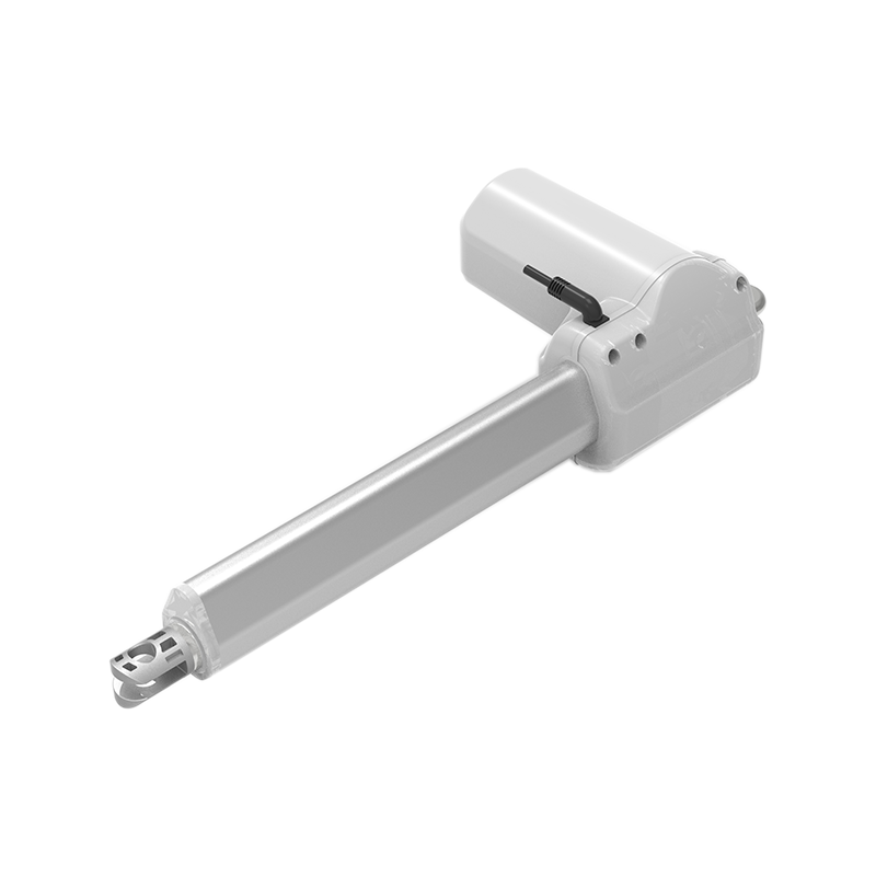
Max. load: 6000 N
Voltage:12v/24vdc
IP: IP54
Max. speed: 42 mm/s
This page is the main selection entrance for GEMING medical linear actuator systems. It is intended for OEM hospital beds, home-care beds, treatment chairs, patient-handling equipment, rehabilitation equipment, and diagnostic platforms.
A complete system may include one or more electric actuators, a control box, a handset or nurse control, optional foot controls, an emergency-stop input, and battery backup. Final configuration depends on the equipment mechanism, load, stroke, speed, duty cycle, mounting geometry, control logic, cleaning conditions, and safety requirements.
For short-stroke, space-constrained mechanisms such as headrests, access panels, small positioning modules, and auxiliary adjustments. Start here when installation space and low moving mass are more important than maximum thrust.
For backrest, leg-rest, tilt, and other articulated bed or care-chair movements. Configurations can be selected by push-pull load, retracted length, stroke, speed under load, mounting direction, and control compatibility.
For mechanisms with higher axial loads, including bed-height linkages, patient-handling equipment, and heavy treatment furniture. High-force selection must include the complete linkage geometry because the actuator force changes as the mechanism angle changes.
For equipment that combines two movements in one integrated drive unit, such as back and leg adjustment in an electric bed frame. Confirm the required travel of each output, holding behavior, control-box compatibility, and manual or emergency release requirements.
| Configuration item | Available direction | What the OEM should provide |
|---|---|---|
| Actuator structure | Compact, standard rod, high-force rod, or dual actuator | Mechanism drawing and available installation envelope |
| Load class | Low-force adjustment through high-force configurations up to 8000 N | Running load, holding load, load direction, and linkage geometry |
| Stroke | Short-stroke and extended-stroke options, typically 10-1500 mm depending on family | Required travel, end clearance, and retracted length |
| Speed | Approximately 4.5-150 mm/s depending on load and transmission | Required travel time under the real operating load |
| Power | 12 VDC or 24 VDC actuator options | Available supply, peak current, and backup-power requirement |
| Protection | IP43, IP54, or IP65 configurations depending on actuator family | Cleaning method, liquid exposure, dust, and operating environment |
| Feedback | Built-in limits and optional Hall feedback on selected configurations | Position reporting, synchronization, and fault-detection needs |
| Controls | Single or multi-actuator control boxes; handset, nurse, foot, or emergency controls | Number of movements, user roles, lockout logic, and emergency behavior |
Important: the maximum load, longest stroke, highest speed, and highest ingress-protection rating belong to different configurations. They must not be combined into one assumed product specification.
Review the wider GEMING Medical & Care application area, or compare the full electric linear actuator range when the mechanism needs a different form factor.
Start with your equipment type, what needs to move, and your contact email. Select the number of powered movements, or choose “Not sure.” Unknown load, stroke and speed values can stay blank.
Send a medical configuration request
Share the details you already know through the medical configuration inquiry form. GEMING will review the equipment task and narrow the actuator system options for further engineering discussion.
A medical linear actuator is a component of the final equipment. Suitability, risk controls, cleanability, electrical safety, mechanical safety, and regulatory compliance must be assessed and validated for the completed medical or care system. A component option should not be treated as system certification.
There is no single best model for every bed movement. Backrest, leg-rest, tilt, and height functions can require different loads, strokes, speeds, installation lengths, controls, and emergency behavior.
Yes, selected control boxes can operate multiple actuator channels. The number of channels, voltage, synchronization, handset functions, and fault behavior must match the equipment design.
For an initial review, describe the equipment and movement, then provide a contact email. During engineering selection, share any available mechanism drawing, load, stroke, closed length, speed, duty cycle, voltage, controls, mounting, cleaning and fault-response requirements.
Not automatically. Force, speed, screw lead, motor, stroke, retracted length, duty cycle, and protection level are configuration-dependent and must be checked together.
| Family | Primary selection purpose | Typical configuration range |
|---|---|---|
| Compact actuator | Short-stroke auxiliary adjustment in limited space | Low-force, short-stroke, high-speed options |
| Standard medical-bed actuator | Backrest, leg-rest, tilt, and care-chair movement | 12/24 VDC; configurable force, stroke, speed, limits, and feedback |
| High-force actuator | Bed-height linkage, patient handling, and heavier treatment furniture | Up to 8000 N depending on configuration and mechanism geometry |
| Dual actuator | Two integrated bed-frame movements | Separate travel outputs with matched control system |
Final values depend on the selected actuator family. Maximum values cannot be combined into one assumed configuration.
Describe the equipment, the powered movements and the number of motors. Add any known load, stroke, closed length, voltage and control requirements. A mechanism drawing helps the engineering review.
Yes. Review the complete motion chain, including the motor count, voltage, input functions, feedback and required emergency behavior. Connector appearance alone does not establish compatibility.
Download the medical bed fast selection guide (PDF) or medical actuator catalog (PDF).
Review ophthalmic equipment actuator selection and CT patient-table lifting columns.
These application guides explain selection considerations. Final suitability depends on your equipment design.