
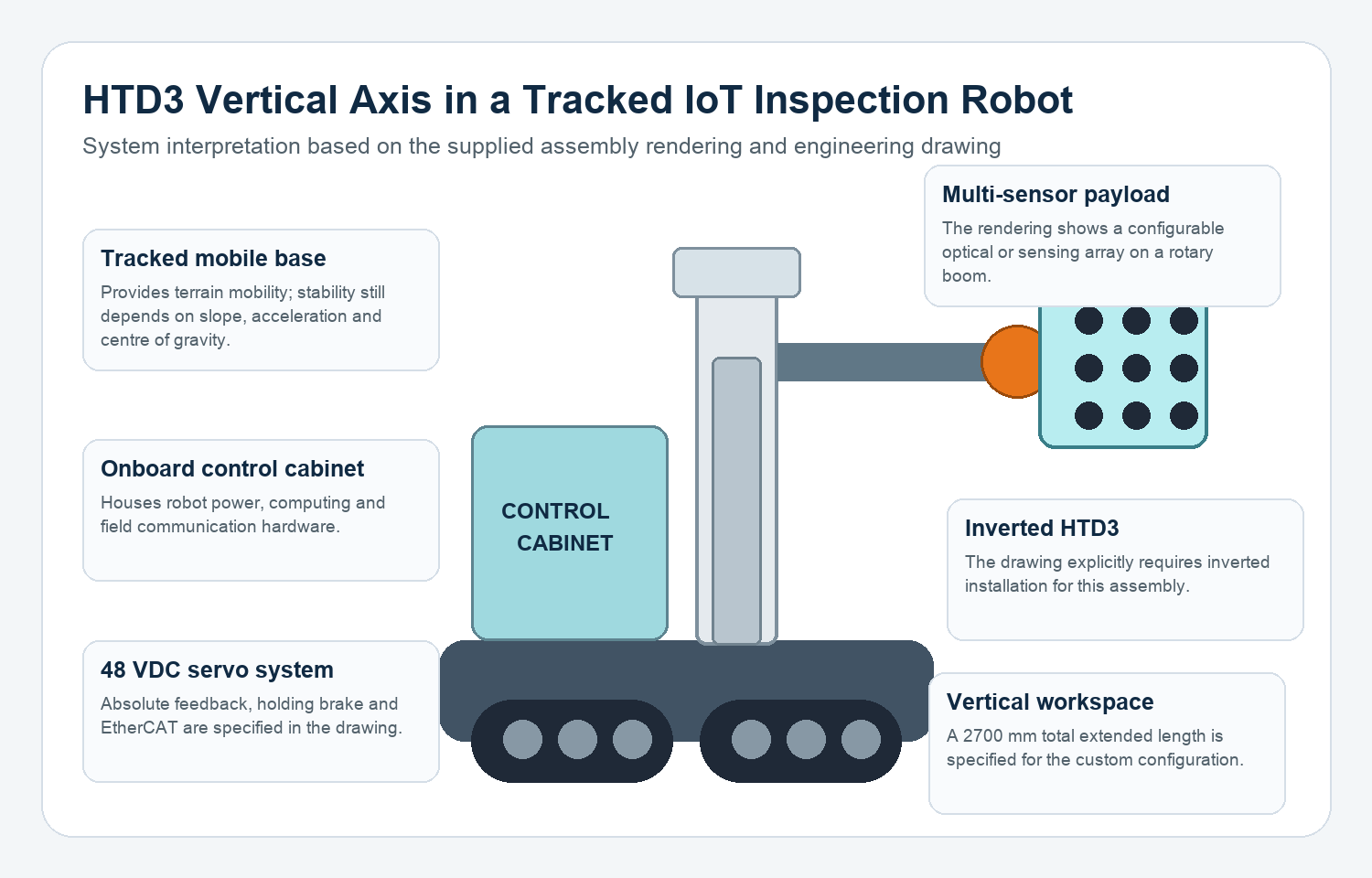
An HTD3 servo lifting column for IoT inspection robots can provide a tracked mobile platform with a fast, position-controlled vertical axis for a multi-sensor payload. Based on the supplied assembly rendering and engineering drawing, this system is best understood as a tracked inspection or data-acquisition robot: the crawler base carries an onboard control cabinet, while an inverted telescopic column raises a rotary boom and a configurable optical or sensor array.
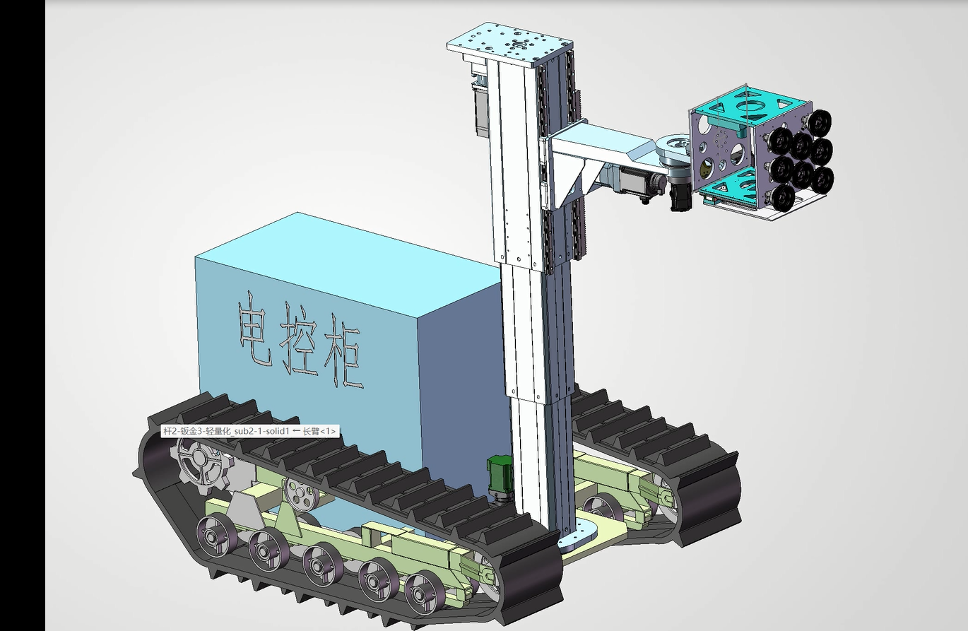
The exact sensing task is not identified in the source files, so it would be inaccurate to label the end module as one specific camera, gas detector or LiDAR. The mechanical architecture can support industrial IoT inspection, remote monitoring, machine-vision data collection, hazardous-area observation or infrastructure survey after the sensor package and environmental requirements are confirmed.
Send GeMinG your robot layout and sensor payload data for an HTD3 integration review.
How the application works
The tracked chassis moves the robot through the inspection area and keeps heavy components such as batteries, drives and computing hardware close to the ground. At the work point, the HTD3 raises the boom to the required height. The boom then changes the horizontal reach or viewing direction of the sensor array. This combination gives the robot three useful capabilities:
- Low travel height while the column is retracted.
- Adjustable sensing height without permanently increasing the chassis profile.
- Controlled positioning of a heavy or offset payload above obstacles and equipment.
This is more demanding than simply lifting a centered mass. The boom places the sensor package away from the column centerline, creating bending moment. Track movement, braking and uneven ground can add dynamic loads. The electric lifting column must therefore be selected as part of the complete robot structure.
Verified HTD3 project configuration from the PDF
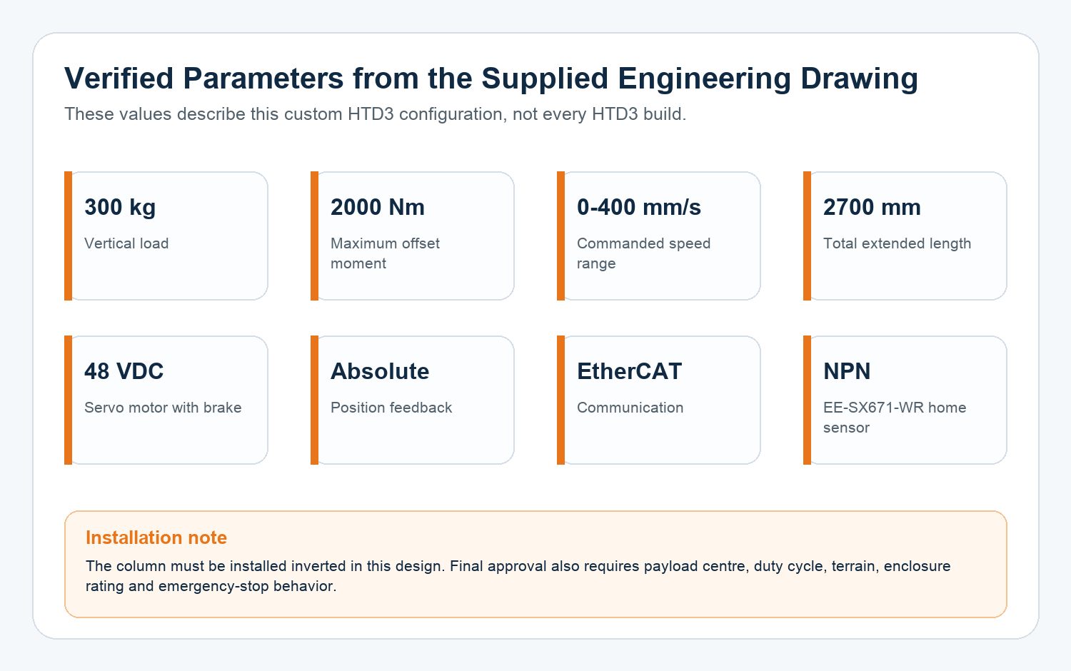
The supplied one-page engineering drawing provides a clear set of project-specific requirements. These values describe this custom assembly and should not be treated as universal limits for every HTD3 configuration:
- Installation: inverted mounting is required.
- Servo drive: 48 VDC motor with holding brake.
- Feedback and network: absolute position feedback with EtherCAT communication.
- Vertical load: 300 kg.
- Maximum offset moment: 2000 Nm.
- Commanded speed range: 0-400 mm/s.
- Total extended length: 2700 mm.
- Home reference: EE-SX671-WR NPN photoelectric switch.
Why the 48 VDC servo and EtherCAT combination fits a mobile robot
A 48 VDC architecture can align with the power systems commonly used in AGVs, AMRs and mobile robots. The holding brake helps the vertical axis maintain a safe mechanical state when commanded to stop or when the drive is disabled, subject to the final safety design. Absolute feedback allows the controller to know the lift position without relying only on an incremental count after power-up.
EtherCAT gives the robot controller a deterministic industrial network for commands, feedback and status. In this application, the column can be coordinated with the tracked base and boom rather than operated as an isolated up/down device. For example, the machine builder can restrict chassis speed while the column is extended, prevent boom rotation outside an approved height range, and command the column to a transport position before the robot moves through a doorway.
The important engineering issue is moment, not load alone
A 300 kg vertical-load figure does not mean that every 300 kg sensor assembly is acceptable. A centered payload and a payload mounted at the end of a long boom create very different stresses. A useful first estimate for static gravity moment is:
Moment (Nm) = moving mass (kg) x 9.81 x horizontal centre-of-gravity offset (m)
For example, a 120 kg moving assembly with its centre of gravity 0.6 m from the column creates about 706 Nm before acceleration or shock is included. This is below the drawing’s 2000 Nm limit, but it is not a final approval. Vertical acceleration, rapid braking, boom rotation, guide deflection, track vibration and floor slope can all increase the real demand.
Interactive preliminary load check
Adjust the payload mass, centre-of-gravity offset, speed and extension below. The tool compares static gravity moment with the drawing value and lists additional checks. It deliberately does not generate an automatic product approval.
Product Parameter Selection Example
Assume the complete moving assembly consists of the boom, rotary joint, cables, mounting frame and sensor package, with a combined mass of 120 kg and a worst-case horizontal centre-of-gravity offset of 0.6 m. The preliminary static moment is approximately 706 Nm. If the robot requires 2200 mm total working height and 160 mm/s vertical motion, the next step is not simply to approve the lift. GeMinG would review the acceleration profile, cycle frequency, column overlap, mounting-plate stiffness, cable drag, brake sequence and base stability.
If the same payload moves farther outward, the moment rises in direct proportion to offset. If speed or acceleration increases, the dynamic demand also rises. This is why the drawing’s 300 kg load, 2000 Nm moment and 400 mm/s maximum speed must be evaluated as a system rather than three independent promises.
Safety and integration checks before prototype testing
- Mounting orientation: follow the drawing’s inverted-installation requirement and confirm fastener access, lubrication and cable exit direction.
- Mobile stability: calculate the complete robot centre of gravity at maximum extension and worst boom angle.
- Motion interlocks: define permitted combinations of track speed, lift height and boom position.
- Emergency stop: coordinate servo disable, brake engagement and controlled deceleration.
- Cable management: allow enough bend radius and prevent sensor, motor and network cables from snagging through the full travel.
- Environmental protection: confirm dust, water, temperature, corrosion and vibration requirements; the supplied drawing does not state an IP rating.
- Validation: test positioning, deflection, temperature rise and sensor data quality on the complete robot.
Why use a telescopic column instead of a fixed mast?
A fixed mast is mechanically simple, but it keeps the robot tall during travel and can place the sensor package high even when elevation is unnecessary. A telescopic HTD3 can retract for transport and extend only at the inspection point. Compared with a standalone linear actuator, the lifting column also provides a guided structural profile; a linear actuator normally needs a separate guide when it must resist significant side load or moment.
For related mobile sensing design considerations, see GeMinG’s guide to a telescopic mast for mobile robots and AMRs. Early packaging work can also use the multi-stage column height calculator, followed by a full engineering review.
What to send for an HTD3 quotation
- Required retracted, working and maximum extended heights.
- Total moving mass, boom geometry and centre-of-gravity coordinates.
- Target speed, acceleration, moves per hour and daily operating time.
- 48 VDC supply range, available peak current and battery capacity.
- EtherCAT master, drive profile, feedback data and error-handling requirements.
- Track acceleration, braking, maximum slope and terrain vibration.
- Environmental protection and operating-temperature requirements.
- CAD model, mounting interface, cable routing and prototype quantity.
Request an engineering review: GeMinG can evaluate the HTD3 configuration against the complete mobile robot load case and prepare drawings, control options and a prototype proposal.
FAQ
What application is shown in the supplied rendering?
It is best identified as a tracked mobile IoT inspection or data-acquisition robot with an adjustable multi-sensor payload. The exact sensor type is not identified in the drawing.
Why is the HTD3 installed upside down?
The supplied engineering drawing explicitly requires inverted installation. This places the moving telescopic structure and boom in the intended geometry, but the mounting plate and lubrication design must match that orientation.
Can the 300 kg load and 400 mm/s speed be used at the same time?
The drawing lists both limits but does not provide a combined load-speed duty curve. Their simultaneous use must be confirmed from the actual drive ratio, acceleration, duty cycle and thermal test.
How is offset moment estimated?
A preliminary static gravity moment is mass multiplied by 9.81 and horizontal centre-of-gravity offset. Dynamic acceleration, boom rotation, chassis slope and impact require additional engineering analysis.
What information is required for a quotation?
Provide moving mass, centre-of-gravity offset, required heights, speed profile, duty cycle, 48 V power limits, EtherCAT master details, environment, mounting drawing and required quantity.