
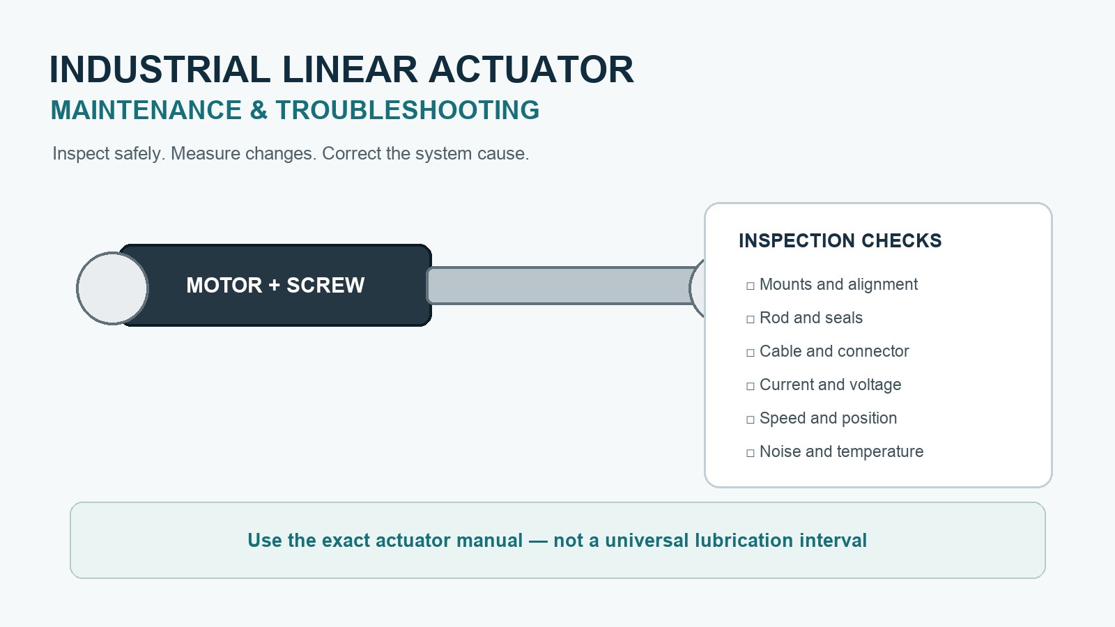
Effective industrial linear actuator maintenance starts with safe isolation, a model-specific manual, and repeatable inspection records.
Check mounting alignment, damage, cables, connectors, and rod condition. Also record current, temperature, speed, position data, and changes in noise.
They should not assume every actuator needs internal lubrication or can be opened in the field.
Use a condition-based service plan. Compare each actuator with its own known-good baseline. Inspect it more often when cycles, load, dirt, washdown, shock, or heat increase.
Safety Before Inspection or Service
An actuator can move unexpectedly or release stored mechanical energy even after a control signal is removed. Before entering a danger zone, follow the machine builder’s energy-control procedure and applicable regulations.
At minimum:
- stop the machine through its normal shutdown sequence;
- isolate electrical and any other hazardous energy sources;
- apply the site’s lockout/tagout procedure;
- restrain or mechanically support raised and suspended loads;
- relieve stored spring, gravity, pneumatic, or hydraulic energy;
- verify isolation before work begins;
- prevent remote commands, automatic restart, or stored motion sequences;
- reapply energy controls after any temporary powered test.
OSHA’s control-of-hazardous-energy guidance explains that electrical, mechanical, hydraulic, pneumatic, thermal, and other stored energy can injure personnel during servicing. A control-panel stop command or emergency-stop button is not automatically an energy-isolating device.
Start With the Correct Product Information
Before creating a maintenance task, identify:
- actuator manufacturer and exact model;
- serial or batch number;
- rated voltage and control interface;
- rated push and pull load;
- stroke and loaded speed;
- duty-cycle or thermal limits;
- feedback type;
- ingress-protection rating;
- approved operating orientation;
- specified lubricant, if external lubrication is permitted;
- replaceable parts and authorized repair level.
This information determines what can safely be inspected, cleaned, lubricated, adjusted, or replaced. Some industrial electric actuators are sealed and pre-lubricated. Their manuals may require only external cleaning and inspection, while prohibiting internal field service.
For help checking whether the original actuator was correctly sized, use the Electric Linear Actuator Selection Guide.
Build a Known-Good Baseline
Troubleshooting becomes faster when commissioning data is recorded before wear or contamination develops.
Record the following under a defined load and motion profile:
- supply voltage at rest and during movement;
- current during extension, retraction, starting, and holding;
- travel time in each direction;
- end-position values and repeatability;
- feedback counts, voltage, or fieldbus position;
- housing or motor temperature after a representative cycle;
- audible noise and vibration;
- controller warnings or fault codes;
- ambient temperature;
- actual load and cycle rate.
A change from the baseline is often more useful than a single reading. Rising current with unchanged load can indicate increased friction, poor alignment, mechanical binding, contamination, or transmission wear.
A slower travel time can also result from voltage drop, controller current limiting, excess load, or cold lubricant.
External Inspection Points
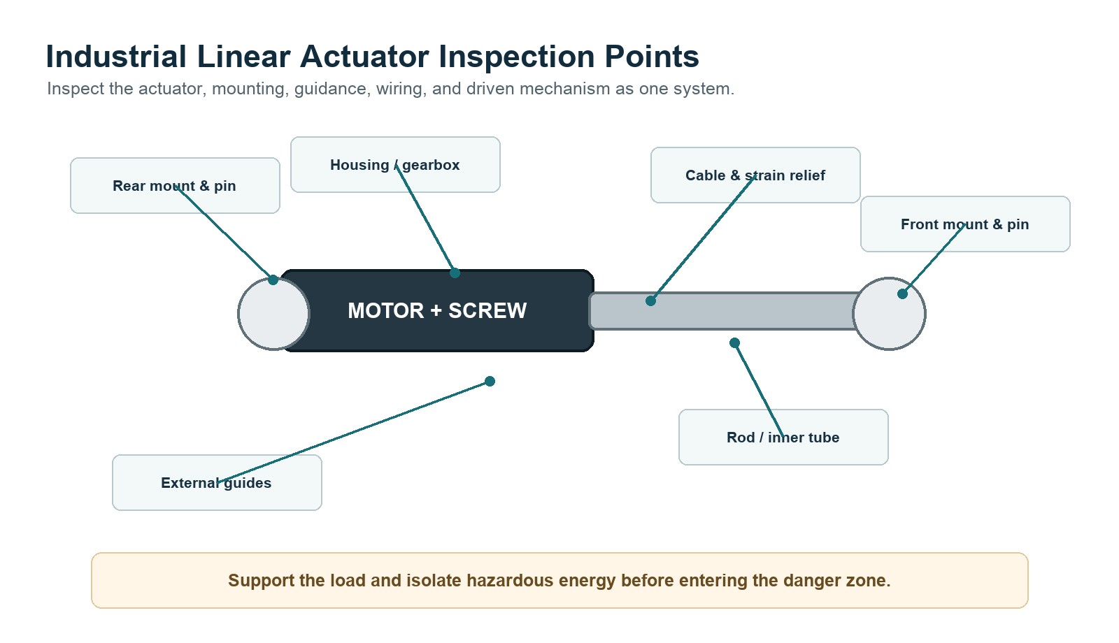
Mounting pins, brackets, and fasteners
Check for loose fasteners, elongated holes, worn pins, cracked welds, distorted brackets, and movement at mounting interfaces. Confirm that pivoting mounts can rotate freely through the complete stroke.
Alignment and side load
The actuator output should not be forced to carry unintended bending or torque. Inspect external guides, hinges, linkages, and bearings. Witness marks, uneven pin wear, rod scoring, or rising current near one part of the stroke may indicate misalignment.
Rod, inner tube, and seals
Look for dents, corrosion, adhesive residue, weld spatter, abrasive contamination, damaged coatings, and seal deformation. Do not operate a damaged rod through a seal. Follow the product manual before applying any cleaner or lubricant.
Housing and gearbox area
Check for impact damage, cracks, loose covers, abnormal discoloration, corrosion, or evidence of overheating. Do not drill, grind, or modify a sealed housing.
Cable, connector, and strain relief
Inspect for crushed insulation, sharp bends, abrasion, loose pins, moisture, corrosion, damaged locking features, and tension at the cable entry. Confirm that moving cables have enough bend radius and cannot be pulled at full stroke.
External guides and the machine structure
An actuator may be healthy while the guided load is binding. Inspect rails, bushings, slides, pivots, and the driven mechanism separately.
Functional Checks
After inspection, perform powered tests only under the site’s controlled test procedure.
Check:
- unloaded or safely reduced-load movement when the machine design permits it;
- smooth extension and retraction through the usable stroke;
- loaded speed in both directions;
- current against the commissioning baseline;
- end-limit operation without repeated mechanical impact;
- position feedback and commanded-versus-actual position;
- brake or load-holding behavior using the approved test method;
- abnormal sound, vibration, heat, or intermittent movement;
- controller faults, communication errors, and input status;
- synchronization error where multiple actuators share a load.
Do not repeatedly cycle a stalled or overheating actuator. Repeated resets can turn an alignment, load, or wiring problem into motor, gearbox, screw, or controller damage.
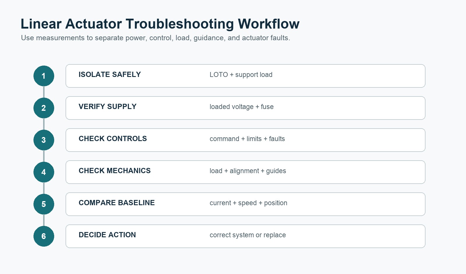
Industrial Linear Actuator Troubleshooting Table
| Symptom | Possible causes | Checks | Appropriate action |
|---|---|---|---|
| No movement and no motor sound | No supply, open fuse, loose connector, control interlock, communication fault, limit input active | Measure voltage at the actuator during a command; inspect fuse, connector, interlocks, and controller status | Restore the correct supply or control condition; do not bypass safety circuits |
| Motor sound but no output movement | Mechanical jam, coupling or gear damage, excessive load, internal transmission fault | Isolate energy; separate the driven mechanism when approved; inspect linkage and compare load with rating | Remove external binding or replace the actuator through an authorized service route |
| Slow movement | Low voltage, voltage drop, overload, current limiting, friction, low temperature, mechanical wear | Measure loaded voltage/current, travel time, temperature, alignment, and guide resistance | Correct supply wiring, load, alignment, or environmental cause before replacing components |
| High current | Excess load, side load, poor alignment, damaged guides, internal friction, stalled motion | Compare extension/retraction current with baseline; inspect the mechanism across the full stroke | Correct the load path; stop testing if current or temperature exceeds approved limits |
| Intermittent movement | Cable break, loose connector, thermal protection, controller fault, moisture ingress | Flex-test cable only when safely de-energized; inspect logs, temperature, connector, and supply stability | Repair wiring or replace damaged components; investigate the thermal or ingress cause |
| Abnormal noise or vibration | Loose mounting, dry external joint, worn pin, gearbox or screw wear, structural resonance | Localize the sound; inspect mounts and guides; compare unloaded and loaded behavior | Tighten or replace external hardware; seek authorized actuator service if noise is internal |
| Position error | Feedback wiring fault, sensor drift, backlash, loose coupling, controller scaling, missed reference | Compare commanded and actual position; inspect feedback supply, signal, scaling, and mechanics | Correct wiring/scaling or replace the faulty feedback/actuator component |
| Stops before end of travel | Current limit, obstruction, limit switch, software limit, thermal protection, insufficient voltage | Check controller flags, current, voltage, temperature, and physical clearance | Remove the verified cause; never defeat limits without an engineering review |
| Overheating | Excess duty cycle, overload, high ambient temperature, binding, rapid reversals, incorrect supply | Compare cycle profile with rating; measure current, temperature, rest time, and load | Reduce duty or load, correct binding, improve system design, or select a suitable actuator |
Lubrication: Do Not Use a Universal Rule
There is no safe universal instruction to grease every industrial electric actuator.
- A sealed, pre-lubricated actuator may require no internal maintenance.
- A serviceable screw actuator may specify a particular grease, quantity, and interval.
- Pivot eyes, pins, or external guides may need lubrication even when the actuator itself does not.
- Incompatible grease can damage seals, plastics, coatings, or the original lubricant system.
- Excess lubricant can attract contamination or be pushed into areas that should remain dry.
Use only the procedure and lubricant specified for the exact model. If the manual says the actuator is a closed unit, do not open it simply because performance has changed. Investigate load, alignment, power, environment, and external guidance first.
The public LINAK LA36 manual is one example of model-specific guidance. It calls for regular cleaning and checks of pins, wires, rod, housing, plug, and function. It also describes that actuator as a closed unit with no internal service.
Those instructions apply to that product, not automatically to every actuator.
Cleaning and Environmental Inspection
Remove dust and debris using methods compatible with the enclosure and seals. Before washdown:
- verify the exact IP rating and permitted cleaning method;
- follow the specified rod position for cleaning;
- avoid directing high-pressure water at seals or connectors unless explicitly allowed;
- use only compatible cleaning chemicals;
- inspect for trapped water, condensation, or damaged connector seals afterward;
- restore protective caps and cable routing.
Inspection frequency should increase in dusty, abrasive, wet, corrosive, outdoor, food-processing, agricultural, or washdown environments.
Preventive Maintenance Intervals
Do not publish or adopt a fixed interval without operating data. Establish the interval from:
- manufacturer requirements;
- machine risk assessment;
- cycles per day;
- operating hours;
- load percentage and shock events;
- duty cycle;
- temperature;
- dust, water, chemicals, and corrosion;
- history of current, temperature, and position changes;
- consequences of failure.
A practical program can use three levels:
Shift or operator check
Look for obvious damage, abnormal noise, unexpected speed, warning messages, loose cables, or contamination.
Planned inspection
Under controlled isolation, inspect mounts, pins, rod, seals, housing, cable, connector, guides, and recorded performance data.
Condition-triggered engineering review
Start a deeper review when measured data leaves the approved baseline. Watch current, temperature, cycle time, position error, noise, vibration, and fault rate.
Product Parameter Selection Example
Consider an indoor industrial linear actuator moving a guided 1,200 N load through a 300 mm stroke at 25 mm/s. It operates four movements per minute and reports position to a PLC.
The maintenance record should include:
- exact actuator model and rated duty cycle;
- commissioning current during loaded extension and retraction;
- normal travel time;
- motor or housing temperature after a representative production period;
- position repeatability at the tooling;
- mounting-bolt and pin condition;
- guide-rail condition;
- cable route at both stroke limits;
- ambient temperature and contamination level;
- cumulative cycles or operating hours when available.
If loaded current rises, first confirm that load and voltage are unchanged. Then check guides, alignment, pins, and dirt. Do not assume a motor fault too early. If only one direction becomes slow, check gravity, geometry, loaded voltage, and binding.
This is an inspection-planning example, not a universal service interval or product specification.
When Replacement Is Safer Than Continued Service
Stop operation and obtain an engineering or manufacturer review when there is:
- structural cracking or distorted mounting hardware;
- a bent, deeply scored, or corroded rod;
- damaged seals with contamination ingress;
- repeated overcurrent or thermal trips after external causes are corrected;
- unstable feedback or unexplained position loss;
- internal grinding, impact, or gear-skipping noise;
- brake or load-holding failure;
- water or chemical ingress;
- obsolete components that prevent safe repair;
- performance outside the machine’s validated limits.
Do not return the axis to production simply because it moves without load.
Pre-Service Checklist
Prepare:
- actuator model, serial number, and nameplate photo;
- machine and axis identification;
- fault codes and controller logs;
- load, stroke, speed, and duty cycle;
- supply voltage and loaded voltage measurement;
- extension and retraction current;
- ambient and housing temperature;
- photos of mounts, guides, rod, seals, cable, and connector;
- a description of when the symptom occurs;
- recent changes to load, controls, software, wiring, or environment;
- maintenance and replacement history.
For industrial applications, see Linear Actuators for Industrial Automation Lines. To compare electric and fluid-power architectures, read Electric vs Hydraulic Linear Actuators.
Conclusion
A good maintenance plan starts with safe isolation and the correct manual. It also checks alignment, external condition, wiring, and measured trends. Avoid generic grease schedules and repeated reset-and-run tests.
A baseline for current, heat, speed, and position helps locate a fault. The cause may be the actuator, power, controls, mounting, guides, or load.
For a technical review, send the model, load, stroke, speed, duty cycle, fault details, mounting layout, and environment through the GEMING contact page.
Frequently Asked Questions
How often should an industrial linear actuator be inspected?
Use the manufacturer’s requirements and adjust the interval for cycles, load, environment, and failure risk. High-cycle, contaminated, washdown, shock, or high-temperature applications normally require more frequent condition checks than clean, lightly used equipment.
Should a linear actuator screw be greased during maintenance?
Only when the exact product manual permits it and specifies the lubricant and procedure. Many sealed actuators are pre-lubricated and should not be opened or internally greased in the field.
Why does an actuator draw more current than before?
Possible causes include higher load, side load, misalignment, binding guides, contamination, voltage problems, temperature, or internal wear. Compare both directions with the commissioning baseline before replacing the actuator.
Can an actuator be tested after lockout/tagout?
Some troubleshooting requires temporary powered testing, but it must follow the site’s approved energy-control and testing procedure. Personnel must be clear of hazards, and energy controls must be reapplied before service continues.
What information is most useful for actuator troubleshooting?
Provide the model, load, stroke, speed, duty cycle, loaded voltage, current in both directions, temperature, fault codes, position data, mounting photos, and a description of when the symptom occurs.