
A linear actuator limit switch detects or defines an end position so the actuator stops before mechanical overtravel. Correct selection depends on whether the switches are fixed or adjustable, internal or external, mechanically or magnetically operated, and whether they interrupt motor current or send a low-current signal to a controller. The actuator wiring diagram, voltage, current, control method, required stopping accuracy, and failure behavior must be reviewed together.

How a linear actuator limit switch works
During extension or retraction, the moving mechanism reaches a defined position and changes the state of a switch. That change can open the motor circuit directly, operate a relay, or tell a controller to stop output. The switch protects the intended travel endpoint; it is not a substitute for correct mounting, overload protection, or mechanical clearance.
Many compact DC actuators use one limit at each end. The circuit stops movement toward the active endpoint but permits the motor to reverse and move away. This may be achieved with internal wiring and diodes, or with separate controller logic. The behavior cannot be inferred from the number of wires alone, so the model-specific diagram remains the controlling document.
Internal versus external limit switches
Internal limit switches
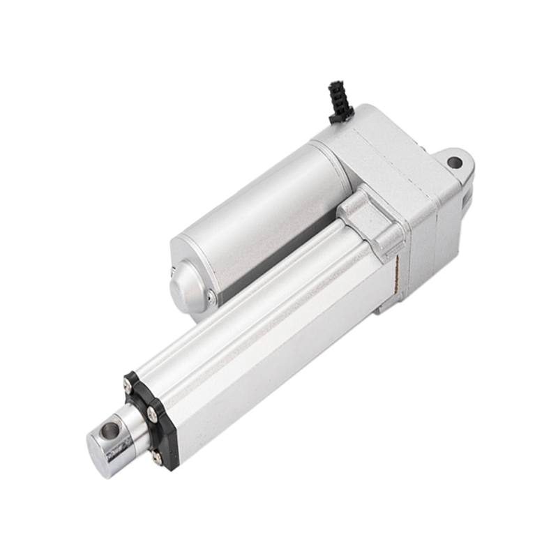
Internal switches are integrated into the actuator housing. They reduce external components and can make installation simpler. In many models, their positions are fixed by the product design and are not field-adjustable. They are useful when the full specified stroke is required and the equipment does not need a variable stopping point.
External limit switches
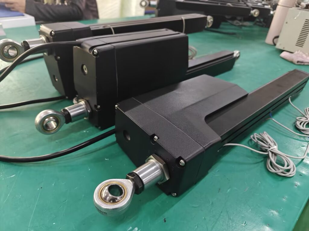
External switches are mounted on the machine or actuator installation. They can be positioned around the actual mechanism and may support adjustable endpoints. However, they require brackets, cable routing, environmental protection, and a control circuit that matches their contact rating and logic.
An external switch can define machine travel before the actuator reaches its own end of stroke. The actuator should still have a safe response if the external switch, bracket, cable, or controller input fails.
Mechanical, magnetic, and software limits
A mechanical microswitch changes state through physical contact. A magnetic limit may use a magnet and sensor without a direct mechanical plunger. A software limit is calculated by a controller from position feedback, pulse count, current, time, or another signal. These methods solve different problems.
- Mechanical limits provide a direct physical switching event but have contact ratings and mechanical tolerances.
- Magnetic limits can avoid exposed contact motion but require correct sensor position, wiring, and magnetic target alignment.
- Software limits can be adjustable in the controller, but their reliability depends on the feedback reference and fault handling.
A robust machine may use more than one layer, such as a controller-defined operating limit plus a separate end-of-travel protection method. The required architecture depends on the consequence of overtravel and the applicable equipment risk assessment.
How two-wire actuators with internal limits are controlled
Many two-wire DC linear actuators change direction when supply polarity is reversed. A relay pair, reversing contactor, or H-bridge controller provides the polarity change. If the actuator includes correctly wired internal end limits, it stops when it reaches the relevant end and can move again when polarity is reversed.
Wiring separate limit-switch leads
When an actuator or external sensor has separate limit leads, first identify whether they are dry contacts, powered sensor outputs, open-collector outputs, or another interface. Then confirm normally open or normally closed behavior, voltage, current, polarity, and the controller input type.
A small sensor contact should not be placed directly in a motor circuit unless its inductive load rating is adequate. Motor current can exceed the running value during starting, reversal, obstruction, or stall. A common approach is to use the switch as a controller or relay input while correctly rated power devices carry motor current. Inductive suppression and grounding should follow the controller and switch documentation.
Normally open versus normally closed contacts
A normally open contact closes when activated. A normally closed contact opens when activated. The correct choice depends on controller logic and the required response to a broken wire or lost power.
A monitored normally closed circuit can make an open cable appear as a fault, but only if the controller is designed to distinguish and act on that state. A normally open circuit may be simpler for some indication tasks. Contact terminology must be interpreted in the switch’s normal, unactuated condition.
Why Hall feedback is not an end limit
Hall sensors commonly provide pulses related to motor or screw movement. A controller can count pulses to estimate relative travel, synchronize actuators, or implement stored positions. A limit switch instead indicates a defined endpoint or stop condition.
Pulse counting can accumulate error if movement is blocked, pulses are missed, or the reference position is lost. Systems using Hall feedback should define homing, end reference, fault detection, and recovery behavior. The custom linear actuator design process explains why controls and failure behavior should be defined before a prototype is released.
Fixed versus adjustable stopping positions
A fixed internal switch is appropriate when the complete product stroke is the required machine stroke. An adjustable endpoint may be necessary when the same actuator platform serves several machine layouts, when the equipment must stop before full travel, or when commissioning requires mechanical tuning.
Adjustment introduces its own requirements: accessible mounting, positive locking, tolerance, repeatability, environmental resistance, cable protection, and documented commissioning settings. A controller-defined position can be convenient, but it still needs a reliable reference and a safe response to sensor or software faults.
Common limit-switch problems
- the actuator stops in one direction because an end limit is active;
- incorrect polarity or relay logic prevents movement away from the endpoint;
- a low-current switch is damaged by direct motor current;
- an external bracket moves and changes the stopping point;
- a broken wire is interpreted as a normal open state;
- voltage drop or controller current limiting is mistaken for a limit event;
- mechanical binding activates overload protection before the limit is reached;
- Hall pulses are treated as an absolute position without a reference routine;
- stopping distance is ignored near a hard mechanical boundary.
The industrial linear actuator maintenance guide provides a structured way to separate electrical, mounting, load, and wear-related symptoms.
Commissioning and validation checklist
- verify the exact actuator, option code, drawing, and wiring diagram;
- confirm switch type, contact state, voltage, and current rating;
- check extension and retraction direction before connecting the mechanism;
- measure terminal voltage and current under load;
- operate each limit repeatedly at low speed or controlled conditions first;
- confirm that the actuator can move away from an active endpoint;
- measure stopping position, repeatability, and worst-case overtravel;
- test broken wire, lost feedback, obstruction, and power-loss behavior as required;
- record final switch settings, bracket positions, and controller parameters.
Information to prepare before requesting a wiring review
- actuator model, option code, voltage, and wiring diagram;
- working and peak load, stroke, and loaded speed;
- fixed or adjustable endpoint requirement;
- controller, relay, or H-bridge model and input type;
- required end indication and intermediate position feedback;
- cable length, connector, grounding, and environmental exposure;
- available mechanical clearance and acceptable stopping tolerance;
- required response to a broken wire, blocked mechanism, or sensor fault.
Conclusion
A reliable linear actuator limit switch system starts with the exact actuator circuit and machine risk, not a generic wire-color assumption. Confirm the endpoint type, contact interface, motor current path, reversal behavior, stopping distance, feedback needs, and fault response. For a model-specific review, send the actuator requirement, mechanism drawing, controller information, voltage, current, stroke, load, and endpoint logic through the GEMING contact page.
Frequently Asked Questions
What does a linear actuator limit switch do?
It detects or defines an end position and causes the motor or controller to stop movement in that direction. The exact behavior depends on the actuator circuit and control wiring.
Are built-in linear actuator limit switches adjustable?
Some designs use fixed internal switches and others provide adjustable or externally mounted limits. Check the model drawing and wiring document instead of assuming adjustability.
How do you wire a two-wire actuator with internal limit switches?
Many two-wire DC actuators extend and retract by reversing polarity, while the internal circuit stops travel at each end. Verify the manufacturer wiring diagram, voltage, current, and controller behavior.
Can a limit switch stop both actuator directions?
An end limit normally stops travel toward that endpoint while still allowing movement away from it. Whether this is achieved internally or through a controller depends on the circuit.
Is a Hall sensor the same as a limit switch?
No. A limit switch identifies an endpoint, while Hall pulses usually provide relative movement feedback. A controller may use Hall data for position logic, but it still needs defined end-of-travel behavior.