
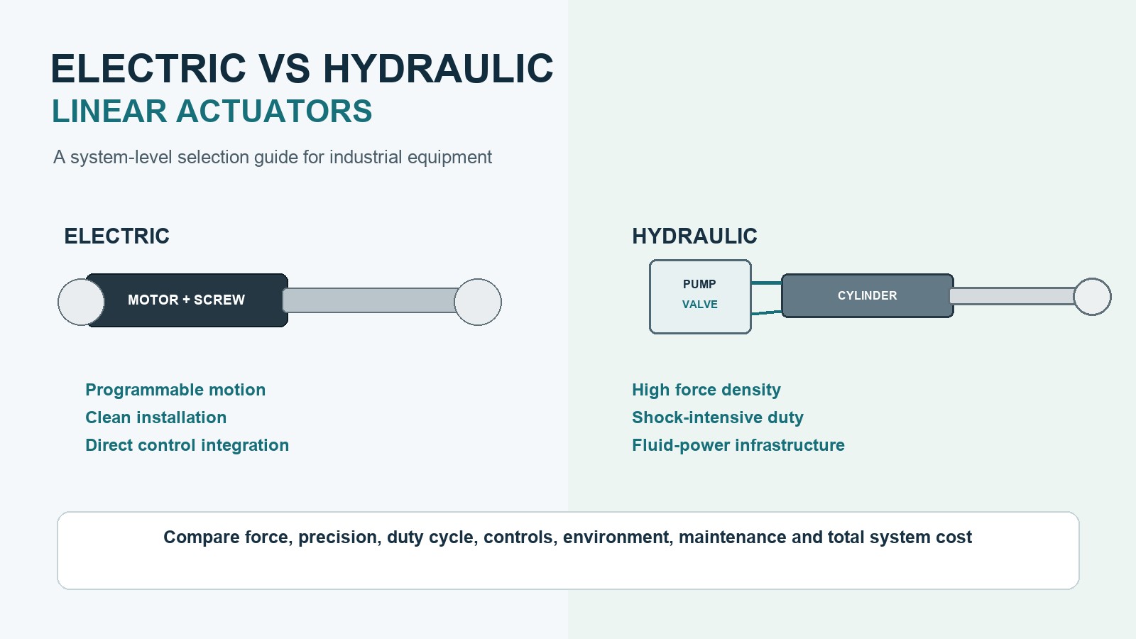
When comparing electric vs hydraulic linear actuators, the right choice depends on more than maximum force.
Also check position accuracy, duty cycle, available power, space, controls, environment, service skills, and total system cost.
Hydraulics often fit machines with very high force or severe shock. Electric systems often fit clean machines that need repeatable motion and simple digital control.
This guide explains the practical differences without treating either technology as universally better.
Quick Answer
Choose electric actuation for controlled point-to-point motion. It also fits tasks that need feedback, programmed moves, clean operation, or a simple PLC link.
Choose hydraulics when very high force must fit in a small space. It may also fit severe shock loads or a machine that already has hydraulic power.
The final decision should be based on the complete motion cycle and system architecture—not actuator force alone.
How Electric Linear Actuators Work
An electric linear actuator converts rotary motor motion into linear travel. A typical system contains:
- an AC, DC, stepper, or servo motor;
- a gearbox when additional torque reduction is required;
- a lead screw, ball screw, or roller screw;
- a translating nut, rod, or guided carriage;
- limit switches or position sensors;
- a controller, drive, or PLC interface.
Motor rotation drives the screw mechanism, moving the output rod or carriage along a defined stroke. Position, speed, acceleration, and stopping points can be controlled when suitable feedback and electronics are included.
For a broader introduction, see What Is a Linear Actuator?.
How Hydraulic Linear Actuators Work
A hydraulic linear actuator normally uses pressurized fluid to move a piston inside a cylinder. The complete system may include:
- a hydraulic cylinder;
- a pump and electric motor or engine-driven power source;
- a reservoir;
- control and relief valves;
- hoses, pipes, seals, and filters;
- position or pressure sensors when closed-loop control is required.
Pressure acting on the piston area generates linear force. Directional valves control extension and retraction, while flow control influences speed.
Hydraulic systems can deliver high force in demanding machines. Do not judge the cylinder alone. Include the power unit, valves, fluid circuit, cooling, and service needs.
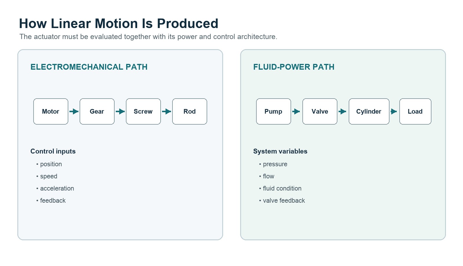
Electric vs Hydraulic Linear Actuators: Main Differences
| Decision factor | Electric linear actuator | Hydraulic linear actuator |
|---|---|---|
| Force capability | Suitable for a wide range of light- to high-force applications, depending on screw, motor, gearbox, and structure | Commonly selected for very high force and high power density |
| Positioning | Direct integration with encoders, potentiometers, Hall sensors, and servo controls | Precise control is possible, but typically needs proportional or servo valves, sensors, and hydraulic control expertise |
| Motion programming | Speed, position, acceleration, and motion profiles can be programmed with a suitable drive | Motion profiles depend on valve, pump, flow, pressure, and feedback configuration |
| Cleanliness | No operating-fluid circuit at the point of motion | Fluid leakage and hose or seal maintenance must be considered |
| Routine maintenance | Often limited to inspection and lubrication requirements defined for the product | Fluid condition, filters, seals, hoses, fittings, and leakage require attention |
| Standby energy | Power can often be limited when the actuator is not moving, depending on holding method | A conventional central hydraulic system may keep a pump operating; accumulator and variable-pump designs can change this |
| Shock-load tolerance | Must be checked against screw, gearbox, brake, housing, and mounting limits | Often well suited to shock-intensive heavy machinery when correctly designed |
| Installation | Requires electrical power, drive/control hardware, and load-appropriate mounting | Requires a fluid power circuit in addition to the cylinder |
| Noise | Mainly motor, gearbox, brake, and structure-borne noise during movement | Pump, motor, valves, and fluid flow may contribute to system noise |
| Failure considerations | Electrical faults, overheating, screw wear, gearbox damage, or sensor faults | Leaks, contamination, pressure loss, seal wear, hose failure, or valve faults |
These are general tendencies. Actual performance depends on the complete design and operating conditions.
When Electric Linear Actuation Is Usually the Better Fit
The machine needs repeatable positioning
Electric actuators are well suited to equipment that moves between defined positions or requires controlled speed and acceleration. With appropriate feedback, the controller can monitor position and coordinate the actuator with other machine functions.
Typical examples include:
- production-line adjustment;
- inspection and test fixtures;
- adjustable workstations;
- mobile robot mechanisms;
- agricultural covers and gates;
- access panels and equipment hatches;
- lifting and positioning modules.
See Linear Actuators for Industrial Automation Lines for application considerations.
Clean operation matters
Medical equipment, laboratories, food-related machinery, indoor automation, electronics manufacturing, and finished-product handling may not tolerate hydraulic-fluid leakage. Electric actuation removes the hydraulic circuit from the motion system, although normal mechanical lubrication and enclosure requirements still apply.
The controls are primarily electrical
An electric actuator can often connect more directly to relays, PLC outputs, motor drives, CAN-based systems, or other machine controls. The exact interface depends on the motor, feedback device, controller, and safety requirements.
Maintenance access is limited
Remote installations and enclosed equipment may benefit from eliminating pumps, reservoirs, filters, valves, and hydraulic hoses. The electric actuator must still be selected for realistic load, duty cycle, temperature, ingress protection, and service life.
When Hydraulic Actuation Is Usually the Better Fit
Very high force is required in a compact cylinder
Hydraulic cylinders are common in presses, construction machines, and heavy material handling. These tasks often need high force from a compact cylinder.
The machine already has hydraulic infrastructure
An extra hydraulic axis may be practical when the machine already has a suitable power unit and fluid circuit. Include its valves, filters, cooling, and service plan. Compare any electric replacement at full-system level.
Severe shocks and overloads are expected
Hydraulic systems are common in rugged machines with shock and changing loads. Relief valves can limit excess pressure. The design still needs checks for structure, stability, and safe failure.
Continuous heavy operation dominates the cycle
Hydraulics may still fit some high-force, high-duty tasks. An electric option may also work. Check screw life, motor heat, gearbox rating, braking, lubrication, and cooling against the full cycle.
Precision Is Not a Simple Hydraulic-versus-Electric Question
Electric systems can simplify precise positioning. The motor, feedback sensor, and controller can form one digital motion system.
Hydraulic axes can also use accurate closed-loop control. They need the right sensors, proportional or servo valves, and fluid circuit.
The useful comparison is therefore:
- required positioning tolerance;
- repeatability;
- speed regulation;
- response time;
- load variation;
- acceptable overshoot;
- control-system complexity;
- commissioning and maintenance capability.
Avoid selecting a technology from a generic “precise” or “not precise” label.
Energy Use Must Be Compared Over the Full Duty Cycle
Energy efficiency depends on how the complete machine operates.
An electric actuator uses most of its energy while it moves. Holding a load may still need a brake, self-locking drive, or motor torque.
A basic hydraulic system may lose energy in the pump and valves. Losses can continue when the power unit runs with no axis moving. Variable-speed pumps and load-sensing designs can reduce this waste.
For a fair comparison, estimate:
- force throughout extension and retraction;
- travel distance and speed;
- movements per hour;
- acceleration and deceleration requirements;
- holding time under load;
- standby time;
- motor, drive, pump, and valve efficiency;
- cooling or heating loads;
- maintenance-related downtime.
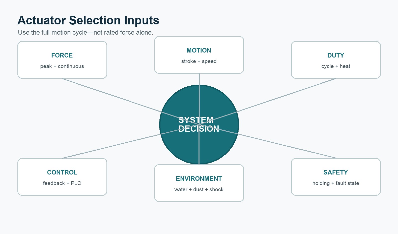
Important Selection Considerations
Load and force
Define the actual axial load in both directions. Include friction, acceleration, external moments, shock factors, and any load created by an unfavorable linkage angle. Do not size an actuator only from the static weight.
Stroke and installation length
Confirm required travel, retracted length, extended length, and surrounding clearances. Long strokes may require additional guidance or anti-buckling review.
Side load and guidance
Many actuator rods are intended mainly for axial loading. If the mechanism introduces side load, torque, or bending moment, use external guides or a guided actuator structure.
Duty cycle and thermal behavior
Document movement time, rest time, cycles per hour, ambient temperature, and load during each part of the cycle. Electric motor temperature and screw life must be evaluated; hydraulic systems may require fluid-temperature and cooling analysis.
Speed and positioning
Specify loaded speed, positioning tolerance, repeatability, synchronization needs, acceleration limits, and whether controlled intermediate positions are required.
Environment
Consider water, dust, washdown, corrosion, vibration, temperature, explosive atmospheres, and outdoor exposure. Required protection must be verified for the selected model rather than assumed from the technology type.
Safety and load holding
Determine what must happen during power loss, control failure, hose failure, sensor failure, or mechanical damage. The design may require brakes, locking devices, counterbalance valves, mechanical stops, redundancy, or external load supports.
Product Parameter Selection Example
Consider an automated fixture that must move a 1,200 N axial load through a 300 mm stroke:
- target loaded speed: 25 mm/s;
- four movements per minute;
- each movement lasts approximately 12 seconds;
- intermediate positioning is required;
- the fixture operates indoors near finished components;
- the machine PLC must confirm actuator position;
- no hydraulic power unit is available.
The first option would usually be an electric actuator. This example needs feedback, PLC control, clean indoor use, and moderate cyclic force.
Final selection still needs more checks. Review dynamic force, screw capacity, duty cycle, motor heat, mounting, side load, stop accuracy, and safe load holding.
The choice may change if the same machine needs several hundred kilonewtons and sees severe impact. An existing hydraulic power unit would also favor a hydraulic cylinder.
This example demonstrates selection logic only; it is not a model recommendation.
Can an Electric Actuator Replace a Hydraulic Cylinder?
Sometimes, but it should not be treated as a direct replacement based only on rated force and stroke.
An engineering review should compare:
- peak and continuous force;
- load direction and shock loads;
- movement speed and acceleration;
- duty cycle;
- retracted and extended dimensions;
- rod guidance and mounting;
- load-holding requirements;
- available electrical power;
- controller and sensor interfaces;
- emergency and manual-operation requirements;
- expected service life and maintenance access.
For electric-actuator sizing fundamentals, use the Electric Linear Actuator Selection Guide.
What to Prepare Before Requesting an Electric Actuator
Prepare the following information before contacting a supplier:
- application description and motion sequence;
- required pushing and pulling force;
- stroke;
- retracted-length limit;
- loaded speed;
- duty cycle and cycles per hour;
- mounting orientation and available space;
- drawings of the linkage and load;
- expected side loads or moments;
- supply voltage;
- feedback and control requirements;
- synchronization requirements;
- ambient temperature and environmental exposure;
- required load-holding and emergency behavior;
- target service life.
Clear operating data is more useful than asking for the “strongest” actuator.
For service planning, use the Industrial Linear Actuator Maintenance Guide. It covers inspection points, baseline data, and fault checks.
Conclusion
The choice between electric vs hydraulic linear actuators should be based on the full machine cycle and support infrastructure.
Hydraulics remain a strong option for very high-force, shock-intensive machinery and installations that already use fluid power.
Electric actuators often fit programmed positioning and clean operation. They also connect well to electrical controls and avoid routine fluid-system service.
For a technical review, send the load, stroke, speed, duty cycle, mounting layout, environment, and controls through the contact page.
Frequently Asked Questions
Are electric linear actuators more precise than hydraulic cylinders?
Electric systems often simplify precise positioning because feedback and motor control can be integrated directly. Hydraulic systems can also be precise, but typically require suitable sensors, proportional or servo valves, and more complex fluid-control engineering.
Which actuator type can produce more force?
Hydraulic cylinders are commonly favored for very high force and high power density. Electric actuators cover a broad force range, but the screw, gearbox, motor, housing, mounting, duty cycle, and thermal limits must all be checked.
Do electric actuators require no maintenance?
No. They may reduce hydraulic-fluid, hose, filter, and seal maintenance, but they still require inspections and any lubrication or service specified by the manufacturer.
Can an electric actuator hold a load when power is removed?
Only if its mechanical design, brake, or external locking system is rated to do so. Self-locking behavior and safe load holding must be verified for the actual model and load direction.
What information is needed to replace a hydraulic cylinder with an electric actuator?
Provide peak and continuous force, stroke, speed, duty cycle, mounting geometry, side loads, available voltage, position-control requirements, environment, and required behavior during power loss.
External technical reference: Comparison of hydraulic, pneumatic and electric linear actuation systems.
Engineering Geometry Calculators
Actuator force depends on the mechanism geometry as well as the lifted load. For an early design check, use the scissor lift actuator force calculator for crossed-arm lift mechanisms or the third-class lever actuator calculator when the actuator drives a lever between the pivot and the load. These tools support preliminary comparison; final sizing must also verify dynamic load, friction, duty cycle, mounting strength and safety factor.