
A custom linear actuator design project turns equipment requirements into a controlled product that can be built and tested repeatedly. The process starts with load, stroke, speed, duty cycle, installation space, controls, and operating environment. It then moves through architecture selection, calculations, prototypes, validation, pilot production, and a documented release. Skipping one of these stages may create a sample that moves correctly but cannot meet life, safety, cost, or production requirements.
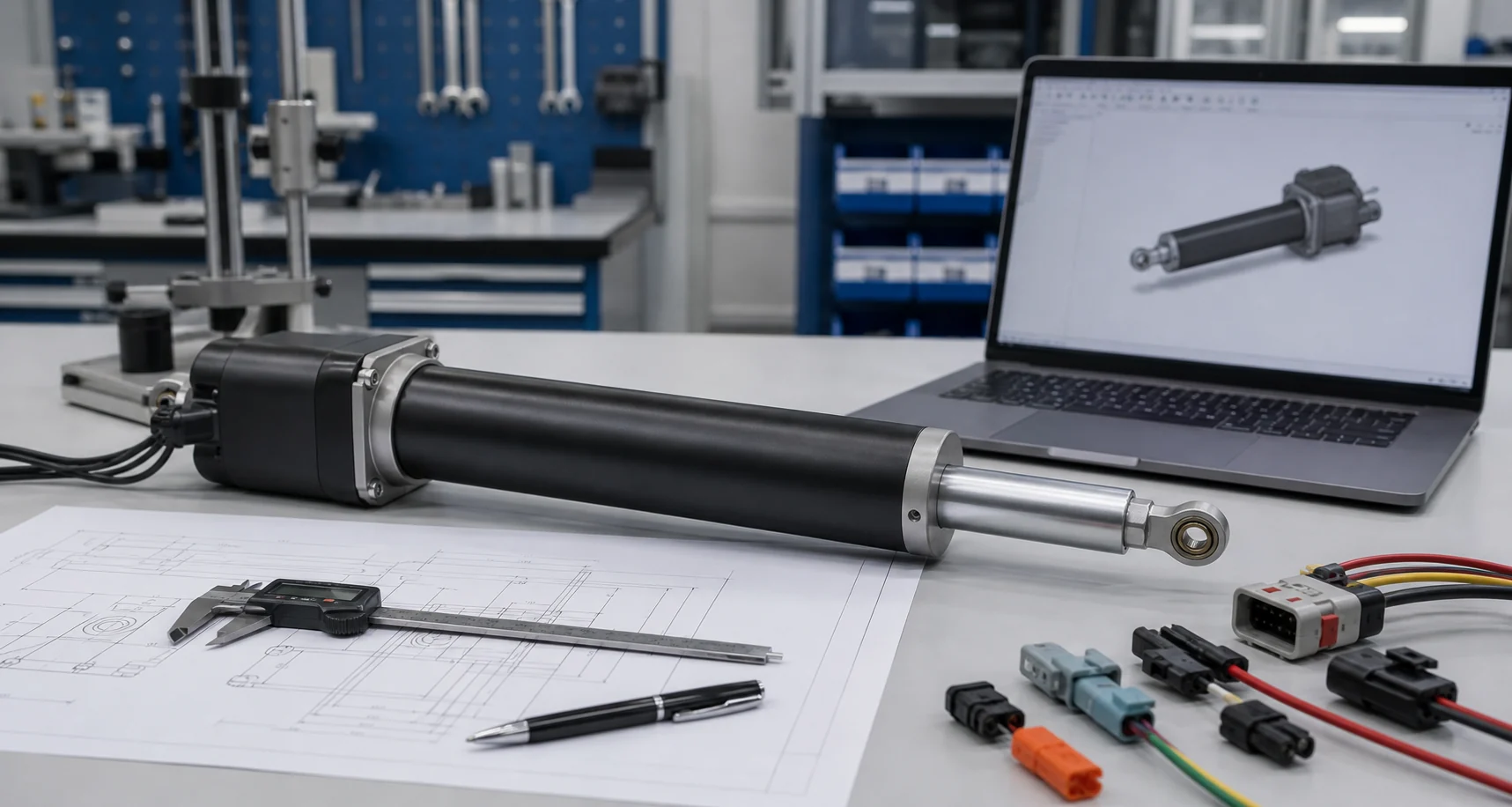
Custom linear actuator design process at a glance
A practical OEM development flow has eight connected stages:
- define the equipment and motion requirement;
- convert the application into actuator performance targets;
- choose a proven platform or a new architecture;
- size the screw, motor, gears, structure, and electrical system;
- release a controlled prototype drawing and sample plan;
- test the actuator in both a bench fixture and the real mechanism;
- confirm manufacturability with a pilot batch;
- freeze the approved specification and change-control process.
These stages are not isolated. A change to speed can alter motor current, screw life, temperature, noise, and controller requirements. Good project control records these links instead of treating each specification as an independent catalog value.
1. Define the equipment before selecting the actuator
The mechanism should be reviewed before an actuator model is chosen. Start with the equipment drawing, movement sequence, mounting points, center of gravity, load path, guidance method, and available space. A free-moving bench load does not represent a hinged cover, guided slide, or misaligned linkage.
The first requirement sheet should separate:
- working load from the worst credible peak load;
- axial force from side load and bending moment;
- required stroke from available retracted length;
- target speed from the complete movement time;
- normal operation from stall, obstruction, or power-loss conditions;
- average duty cycle from the most demanding operating period.
The electric linear actuator selection guide explains these basic inputs in more detail.
2. Convert application needs into measurable targets
Every important requirement should have a value, condition, and acceptance method. “Fast,” “quiet,” or “outdoor” is not enough. A useful specification states the required movement time under load, the acceptable sound condition, the temperature range, the expected water or dust exposure, and how each item will be checked.
Core targets normally include force, stroke, speed, current, linear actuator duty cycle, service life, noise, backlash, holding behavior, ingress protection, and position accuracy. The project should also define which values are required and which are preferences. This distinction prevents a secondary target from forcing unnecessary size, cost, or complexity.
3. Choose between a standard platform and a new architecture
Customization does not always mean designing every component again. A validated platform can often accept a different stroke, mount, cable, connector, feedback device, housing interface, or control option. Reusing proven parts reduces tooling, test scope, and supply risk.
A deeper redesign may be needed when the project requires an unusual retracted length, high load in a small diameter, a special environmental seal, very low noise, nonstandard feedback, or a unique structural interface. The supplier should identify which changes affect only fit and which changes require new performance or life validation.
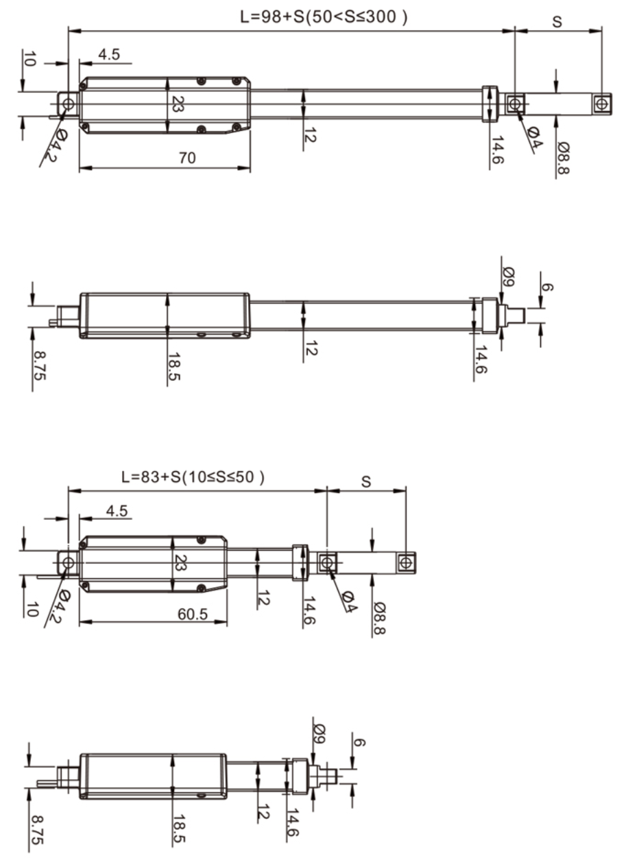
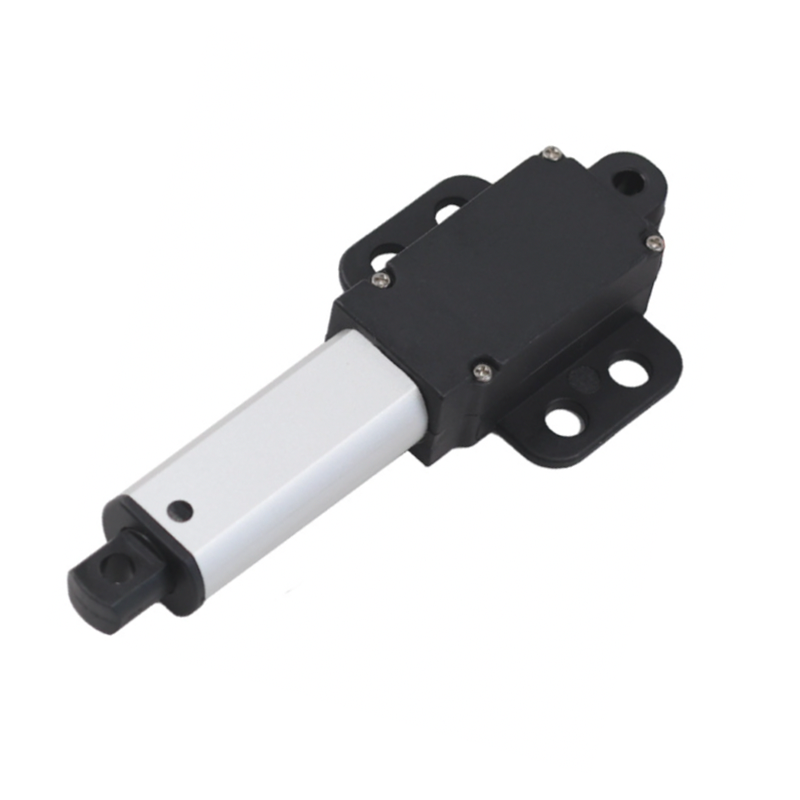
The GEMING linear actuator range provides reference platforms for initial comparison. The HTK15M miniature linear actuator is one example for compact mechanisms, but an application review is still required.
4. Complete the preliminary mechanical and electrical sizing
Actuator sizing is a system calculation. The screw, nut, motor, gear ratio, bearings, housing, rod, mounts, cable, and controller must work together. A higher gear ratio may increase available force, but it can reduce speed and raise movement time. A faster motor may increase current and temperature. A longer stroke can change buckling risk and retracted length.
The preliminary review should check:
- force and torque under normal, peak, and stalled conditions;
- screw life, buckling margin, and expected wear;
- motor speed, current, thermal rise, and available voltage at the actuator;
- gear strength, efficiency, backlash, and noise;
- rod, tube, bearing, and mounting strength;
- static holding, back-driving, braking, and power-loss behavior;
- tolerance accumulation and possible misalignment.
Calculations are screening tools, not final proof. Their assumptions should be confirmed with measured values and application testing.
5. Define controls, feedback, and failure behavior
The electrical interface must be designed with the controller, not added after the mechanical sample is finished. Confirm the supply voltage, running and peak current, polarity reversal, linear actuator limit-switch logic, braking, cable length, connector pinout, and protection against overload or short circuits.
Feedback options may include Hall pulses, a potentiometer, an encoder, or another project-specific sensor. The choice depends on whether the system needs end-position confirmation, relative position, closed-loop control, synchronization, or fault detection. The specification should also state what happens after a lost signal, obstruction, stall, or power interruption.
6. Build a controlled prototype
A prototype should be linked to a drawing revision, bill of materials, firmware or control version, and sample record. Without that link, a successful sample cannot become a repeatable production baseline. The sample plan should state which dimensions and performance values will be measured before shipment.
Prototype testing normally begins on a fixture, then moves to the actual equipment. Fixture tests make force, speed, current, temperature, and noise easier to measure. Equipment tests reveal geometry, guidance, cable routing, controller behavior, vibration, and user-cycle issues that a bench test may miss.
7. Validate the main technical risks
The validation plan should come from the expected failure modes. A long-life industrial mechanism may need load cycling and temperature monitoring. Outdoor equipment may need water, dust, corrosion, cable, and seal tests. A synchronized system may need position-difference limits and fault recovery tests.
Useful validation evidence can include:
- force, speed, current, and movement-time measurements;
- duty-cycle and temperature-rise testing;
- cycle-life testing at defined loads and conditions;
- stall, obstruction, overload, and power-loss behavior;
- noise, backlash, holding force, and position repeatability;
- ingress, vibration, corrosion, or cable-flex testing when required;
- inspection of wear parts after the test.
Not every project needs every test. The goal is to cover the risks created by the actual application, not to collect unrelated certificates.
8. Use a pilot batch before production release
A prototype proves the design concept. A pilot batch proves that the design can be manufactured consistently. The pilot should use controlled drawings, approved parts, defined assembly steps, inspection criteria, and end-of-line tests.
Engineering and quality teams should review any variation between pilot units. Corrective actions should be completed before the final drawing and bill of materials are frozen. Production release should also define lot identification, nonconformance handling, change notification, and records that must be retained.
Product Parameter Selection Example
Consider an automated enclosure that needs a 24 V DC actuator to move a guided panel. The initial targets are a 180 mm stroke, 450 N working load, 18-second movement time, 20% duty cycle, indoor operation, and Hall feedback. The available retracted length is 350 mm.
The design review should first verify the peak load, guidance friction, misalignment, acceleration, loaded supply voltage, controller current limit, mounting-pin strength, and required holding behavior. The supplier can then compare a proven platform with a deeper custom design. The prototype plan should measure force, time, current, temperature, Hall pulse consistency, and stop behavior in the actual enclosure. Only tested conditions and accepted margins should enter the released specification.
Documents needed for a controlled release
A complete development package allows engineering, quality, purchasing, and production to use the same product definition. It normally contains:
- approved product specification and application requirement sheet;
- released drawing with revision and critical characteristics;
- electrical interface, connector, and control information;
- bill of materials and approved component rules;
- prototype, validation, and pilot-batch reports;
- incoming, in-process, and end-of-line inspection criteria;
- packaging, labeling, and lot-traceability requirements;
- change-notification and nonconformance procedures.
These records also help an OEM compare suppliers. The related custom linear actuator manufacturer evaluation guide explains what evidence to request during supplier qualification.
Common development mistakes
- selecting from maximum force without checking speed, current, and life;
- ignoring side load, guidance, or changing linkage geometry;
- using nominal voltage while overlooking cable and controller voltage drop;
- approving a sample without a controlled drawing revision;
- testing only on a bench and not in the real mechanism;
- changing a motor, grease, cable, or feedback device without revalidation;
- starting volume production before pilot variation is understood.
Information to prepare before requesting a design review
- equipment description, drawings, photos, and movement sequence;
- working and peak load with load direction;
- stroke, target speed, and available retracted length;
- mounting points, guidance, linkage geometry, and side-load risk;
- voltage, current limit, controls, feedback, and fault behavior;
- duty cycle, cycles per day, and expected service life;
- temperature, moisture, dust, vibration, corrosion, and cleaning exposure;
- prototype quantity, annual demand, compliance needs, and schedule.
Conclusion
A successful custom linear actuator design is not defined by a sample that moves once. It is defined by clear requirements, linked calculations, controlled drawings, measured validation, repeatable pilot production, and disciplined change management. To discuss a project, send the application drawing, load, stroke, speed, duty cycle, installation space, controls, environment, and expected quantity through the GEMING contact page.
Frequently Asked Questions
What information is needed to start a custom linear actuator design?
Start with working and peak load, stroke, target speed, duty cycle, available voltage, installation space, mounting geometry, environment, feedback needs, expected life, and annual quantity.
How long does a custom linear actuator development project take?
Timing depends on the amount of mechanical and electrical change, prototype tooling, test duration, and approval requirements. A schedule should separate design review, samples, validation, pilot production, and release.
Does a custom actuator always require a completely new design?
No. Many projects begin with a validated actuator platform and change only the stroke, mounts, cable, connector, feedback, or housing interface. Reusing a proven platform can reduce risk.
What should be validated before releasing an actuator for production?
Validate fit, force, speed, current, temperature, duty cycle, holding behavior, controls, environmental exposure, cycle life, and the main failure conditions of the actual mechanism.
Why is a pilot batch needed after prototype approval?
A pilot batch checks whether drawings, parts, assembly steps, inspection criteria, and end-of-line tests can produce the same approved actuator repeatedly.