
Linear actuator duty cycle is the percentage of a defined operating period during which the actuator is commanded to run. It is calculated from running time and rest time, but correct sizing also depends on load, speed, stroke, supply voltage, ambient temperature, starts per hour, mounting, and heat dissipation. The timing percentage is therefore an input to actuator selection, not proof that a particular actuator can survive the application.
What is linear actuator duty cycle?
Duty cycle describes the relationship between active movement and the complete run-rest period. If an actuator runs for 20 seconds and then rests for 40 seconds, one period is 60 seconds and the theoretical duty cycle is 33.3%.
The basic equation is:
Duty cycle (%) = running time ÷ (running time + rest time) × 100
The calculation must use the same time basis as the product rating. A value stated for a short test period cannot automatically be extended to an eight-hour production shift. Also distinguish motor-on time from dwell time while the actuator is stopped. If the actuator must hold a load while powered, that holding condition may still generate heat and must be reviewed separately.
Calculate the motion schedule
Duty Cycle Timing Calculator
Enter one running period and the following rest period. The result describes timing only; it is not a thermal or product approval.
Duty cycle: 33.3% | Repeated cycles per hour: 60.0
Use the tool for an initial timing check. Then compare the result with documented performance under the same load, stroke, speed, voltage, and temperature. Reversing direction, accelerating the load, stopping against an obstruction, or restarting before the unit cools can create more heat than a simple average percentage suggests.
Why the percentage alone is not enough
Two machines can both operate at 25% duty cycle and still impose very different thermal loads. One may make a light movement every few minutes. The other may start under peak load, run near its current limit, reverse immediately, and repeat in a warm enclosure. Their calculated timing is equal, but their motor, screw, gear, bearing, and controller temperatures can be different.
A useful duty-cycle requirement therefore records:
- running time in each direction;
- rest time between movements;
- cycles per hour and the most demanding continuous operating window;
- working, peak, and holding loads;
- stroke and speed under load;
- supply voltage measured at the actuator while running;
- ambient temperature and enclosure ventilation;
- starting, stopping, reversal, braking, and stall conditions.
How load changes temperature
Mechanical load affects the torque and current required from the motor. As current rises, electrical losses and temperature commonly rise as well. Friction, poor guidance, side load, tight seals, misalignment, or a linkage with changing geometry can make the actual load higher than the nominal payload suggests.
This is why the force requirement should be measured or calculated at the most demanding position of the mechanism. The electric linear actuator selection guide explains how force, stroke, speed, mounting, environment, and control requirements should be reviewed together.
How speed and stroke affect the cycle
A longer stroke normally increases running time when speed is unchanged. A higher target speed may shorten the movement, but it can require a different motor, gear ratio, screw lead, current limit, or braking strategy. These changes can alter both available force and heat generation.
Calculate the full movement sequence rather than only one extension. A machine may extend under load, pause, retract with a different load, and start again after a short delay. Add all motor-on periods that occur within the defined cycle. If the operating pattern changes by mode or recipe, calculate the most demanding credible sequence.
Ambient temperature and installation matter
An actuator can reject heat more effectively in cool, moving air than inside a sealed enclosure near another heat source. Sun exposure, hot process equipment, insulation, restricted airflow, or an enclosed motor compartment can raise the starting temperature before the first movement begins.
Mounting can also influence heat flow and mechanical load. A rigid metal structure may conduct heat differently from an insulated bracket. Misaligned clevises or a guided mechanism that binds can increase current. The application review should therefore include both the thermal environment and the complete load path.
Voltage, current, and controls must be checked together
Nominal supply voltage does not guarantee that the same voltage reaches the actuator during movement. Cable length, conductor size, connectors, relays, controller electronics, and the power supply can create voltage drop. Lower voltage may reduce speed, extend running time, or change current behavior, depending on the drive system.
Record running current, peak current, controller current limit, and voltage at the actuator terminals under load. Confirm that the controller, cable, connector, and power supply are rated for the complete cycle. A thermal limit inside the actuator or controller can protect hardware, but repeated thermal trips mean the application or selection needs correction.
What does 100% duty cycle really mean?
A 100% timing calculation means there is no planned rest period. It does not mean every electric actuator can run continuously. Continuous operation must be supported by a rating or validation that matches the actual load, speed, voltage, ambient temperature, cooling, and service-life target.
Do not convert a short-duration intermittent rating into continuous duty by calculation alone. If the machine genuinely requires uninterrupted motion, state the required operating hours, load profile, temperature, and acceptable maintenance interval during the custom linear actuator design process. The resulting solution may need a different motor, transmission, housing, lubrication, cooling approach, or overall actuator architecture.
How to size an actuator for repeated operation
1. Define one complete operating cycle
Write the sequence in seconds: extend, dwell, retract, and rest. Include any powered holding period and immediate reversal. Then calculate cycles per hour and identify the longest period of uninterrupted production.
2. Define the mechanical requirement
Record force throughout the travel, stroke, loaded speed, installation geometry, guidance, side-load risk, and holding behavior. Use the most demanding credible condition, not only the average payload.
3. Define the electrical and thermal conditions
Specify voltage at the actuator, controller limits, cable length, ambient temperature, enclosure, nearby heat sources, and expected airflow. These conditions should match the validation setup.
4. Compare with validated product data
Use a documented rating with a defined load, temperature, and time basis. Product families vary in motor size, screw design, gearing, housing, and intended operating pattern. The GEMING linear actuator range can provide starting platforms, but a model should not be selected from appearance or maximum force alone.
5. Test the actual mechanism
Measure movement time, terminal voltage, running and peak current, motor or housing temperature, and the behavior of the complete machine. Repeat the most demanding sequence until temperature stabilizes or the defined test duration is reached. Inspect for binding, noise, unexpected wear, controller trips, or speed loss.
Product Parameter Selection Example
Consider an automated inspection cover that extends for 12 seconds, pauses unpowered for 8 seconds, retracts for 12 seconds, and rests for 48 seconds before the next cycle. Motor-on time is 24 seconds and the complete cycle is 80 seconds, so the theoretical duty cycle is 30%. The sequence repeats 45 times per hour.
The timing result is only the first requirement. The design review must also verify the peak force near the closed position, loaded speed in both directions, supply voltage at the actuator, controller current limit, ambient temperature inside the enclosure, mounting alignment, and whether the cover creates a changing lever arm. A candidate actuator should then be tested through the complete 80-second sequence at the expected load and temperature. The released specification should state both the timing pattern and the validated conditions.
Examples of different actuator platforms
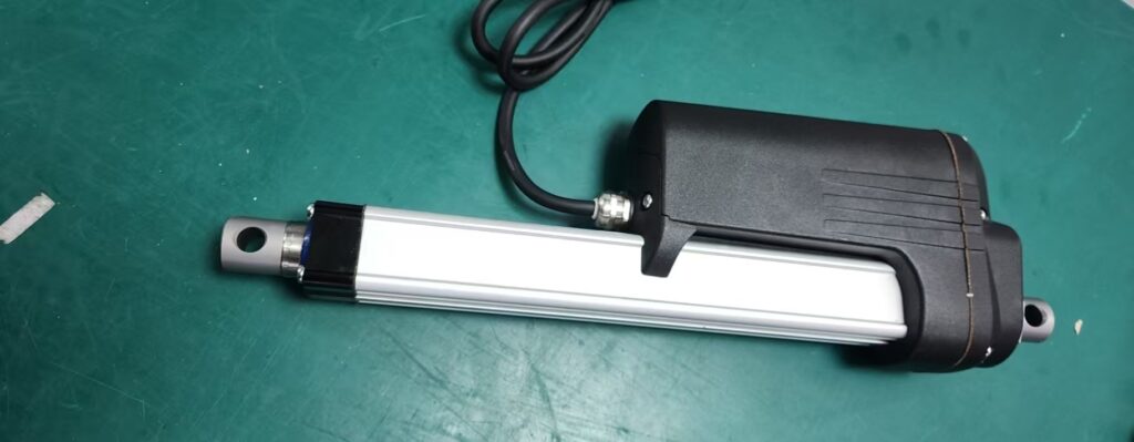
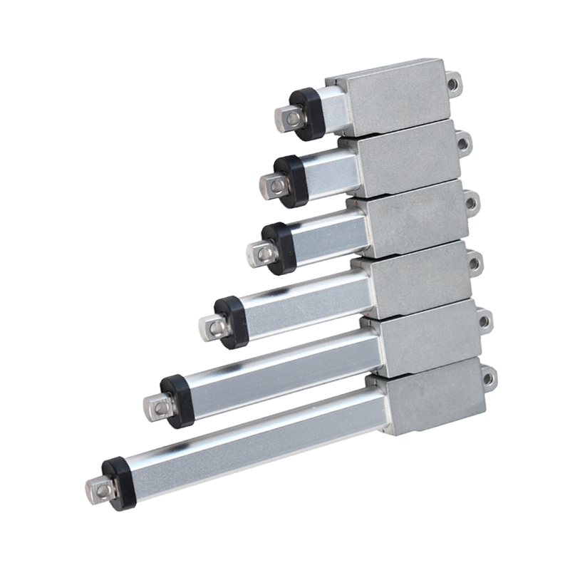
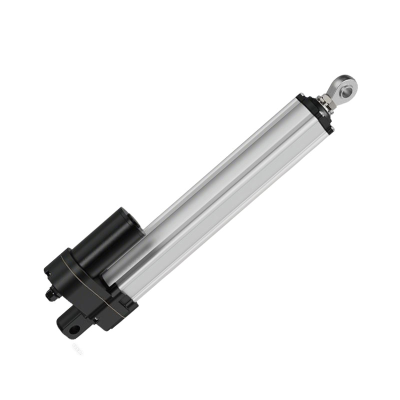
The HTW73 linear actuator, HTK15M miniature linear actuator, and HTW90-YB industrial linear actuator illustrate different physical packages. Their images are included to show real GEMING products, not to assign a common duty-cycle rating. Each application still requires the relevant specification and operating-condition review.
Common duty-cycle sizing mistakes
- using only the average percentage and ignoring starts per hour;
- counting extension time but not powered retraction or holding;
- using no-load speed to estimate loaded running time;
- ignoring voltage drop through the controller and cable;
- treating maximum push force as a continuous operating point;
- overlooking side load, guidance friction, or changing linkage geometry;
- applying a room-temperature rating inside a hot enclosure;
- assuming a lighter load automatically creates an approved higher rating;
- testing one cycle instead of the full thermal operating window.
What to measure during validation
A practical validation record should include the drawing revision, actuator configuration, load, stroke, speed, voltage, current, ambient temperature, starting temperature, cycle timing, and measurement points. Record temperature at defined intervals and note when it stabilizes. If the application has several operating modes, test the most demanding credible mode and any abnormal condition that can reasonably occur.
After testing, inspect mounting pins, rod alignment, cable routing, seals, screw or gear noise, and controller fault history. The industrial linear actuator maintenance guide provides a useful inspection framework for equipment already in service.
Information to prepare before requesting a duty-cycle review
- working and peak load with force direction;
- stroke and loaded movement time in each direction;
- complete sequence with dwell and rest periods;
- cycles per hour, operating hours per shift, and peak production window;
- voltage at the actuator, controller limit, cable length, and connector;
- ambient temperature, enclosure, airflow, moisture, dust, and vibration;
- mounting drawing, guidance method, and possible side load;
- expected life, safety behavior, and acceptable maintenance interval.
Conclusion
Linear actuator duty cycle begins with a simple time ratio, but dependable sizing requires the complete mechanical, electrical, and thermal operating condition. Calculate motor-on time accurately, define the time basis, compare it with validated data, and test the actual mechanism through its most demanding sequence. For an application review, send the load, stroke, speed, cycle timing, voltage, mounting drawing, temperature, and expected life through the GEMING contact page.
Frequently Asked Questions
What does a 25% linear actuator duty cycle mean?
It means commanded running time is one quarter of the defined operating period. For example, 15 seconds running followed by 45 seconds resting is 25%, but the rating is valid only under the stated load, voltage, temperature, and test conditions.
How is linear actuator duty cycle calculated?
Divide running time by running time plus rest time, then multiply by 100. The timing result describes the motion schedule; it does not by itself confirm that an actuator can handle the resulting heat.
Can a linear actuator run continuously?
Only when it is rated and validated for continuous operation at the required load, speed, voltage, mounting condition, and ambient temperature. A calculated 100% command schedule is not a product rating.
Does a lighter load allow a higher duty cycle?
A lighter load may reduce current and heat, but the permitted increase cannot be assumed. Confirm it from validated performance data or an application-specific thermal test.
Why can an actuator overheat below its stated duty cycle?
Possible causes include higher actual load, side loading, repeated starts, low supply voltage, controller limits, poor heat dissipation, high ambient temperature, or a different timing basis from the rating.